


Click the photo to view the full-size version
| Name | Crescent Bridge Davenport, Rock Island & North Western Railway Bridge |
| Built By | Davenport, Rock Island & North Western Railway |
| Currently Owned By | BNSF Railway/Canadian Pacific Kansas City Limited |
| Superstructure Contractor | Phoenix Bridge Company of Phoenixville, Pennsylvania Wisconsin Bridge & Iron Company of North Milwaukee, Wisconsin (North Approach) |
| Substructure Contractor | Charles Stone of St. Paul, Minnesota |
| Design Engineer | Charles Frederick Loweth |
| Length | 2388 Feet Total, 442 Foot Main Span |
| Width | 1 Track |
| Height Above Ground | 20 Feet (Estimated) |
| Superstructure Design | Baltimore Through Truss Swing Span Pennsylvania Through Truss (Spans #5-8) Pratt Through Truss (Spans #1-3) Deck Plate Girder (Span #9) |
| Substructure Design | Stone Masonry and Concrete |
| Date Built | 1898, North Approach Added 1905 |
| Traffic Count | 10 Trains/Day (Estimated) |
| Current Status | In Use |
| Davenport, Rock Island & North Western Railway Bridge Number | 150 |
| Significance | High Significance |
| Documentation Date | 3/27/2015; 9/2/2023 |
In 1897, the Davenport, Rock Island & North Western Railway (DRI&NW) began construction on a 4 mile line, extending from Rock Island, Illinois to Davenport, Iowa. The railroad also constructed a bridge across the Mississippi River between the two cities. The railroad was jointly owned by the Chicago, Milwaukee & St. Paul Railway (Milwaukee Road) and the Chicago, Burlington & Quincy Railway (CB&Q). Between 1898 and early 1900, the Davenport, Clinton and Eastern Railway (DC&E) constructed 34 miles of new railroad, extending from Clinton, Iowa to Davenport, Iowa; roughly paralleling the west bank of the Mississippi River. In early 1901, the Davenport, Rock Island and Northwestern Railway constructed an additional 6 miles of railroad, extending from Rock Island to East Moline, Illinois. Later that year, the Moline and Peoria Railway would construct an additional 7 miles from East Moline to Carbon Cliff, Illinois. The three railroads would become part of the DRI&NW in 1901.
The DRI&NW served as a bridge railroad within the Quad Cities. The railroad provided a critical second crossing of the Mississippi River, and allowed for the Milwaukee Road and CB&Q to interchange with other railroads in the Quad Cities. Both the Milwaukee Road and CB&Q had grown into large railroad networks, with extensive lines throughout the Midwest. In addition to crossing the Mississippi River, the railroad served a diverse variety of industries. The segment between East Moline and Carbon Cliff would be abandoned in the early 20th Century. The Milwaukee Road was often in financial trouble, especially after the
costly Pacific Extension was completed in 1909. In 1925, the company
declared bankruptcy, and reorganized as the Chicago, Milwaukee, St. Paul
and Pacific Railroad in 1928. In 1970, the
CB&Q was merged with the Northern Pacific
Railway and the Great Northern Railway to form Burlington Northern
Railroad (BN). By 1985, a suitor for the Milwaukee Road was being sought, and the Soo
Line Railroad, controlled by Canadian Pacific Railway (CP) purchased the
Milwaukee Road in 1986. In 1996, BN merged with Atchison, Topeka & Santa Fe
Railway
to form BNSF Railway. In 1997, CP would sell the Davenport to Clinton line to I&M Rail Link, which was purchased by the Dakota,
Minnesota & Eastern Railroad (DM&E) subsidiary Iowa, Chicago
& Eastern Railroad (IC&E). The DM&E/IC&E were purchased
by Canadian Pacific in 2008. CP merged with Kansas City Southern
Railway in 2023 to form CPKC. Today, the line to Clinton continues to be operated by CPKC, while the remainder of the trackage is shared by BNSF Railway and CPKC.
View an article describing the construction of this bridge
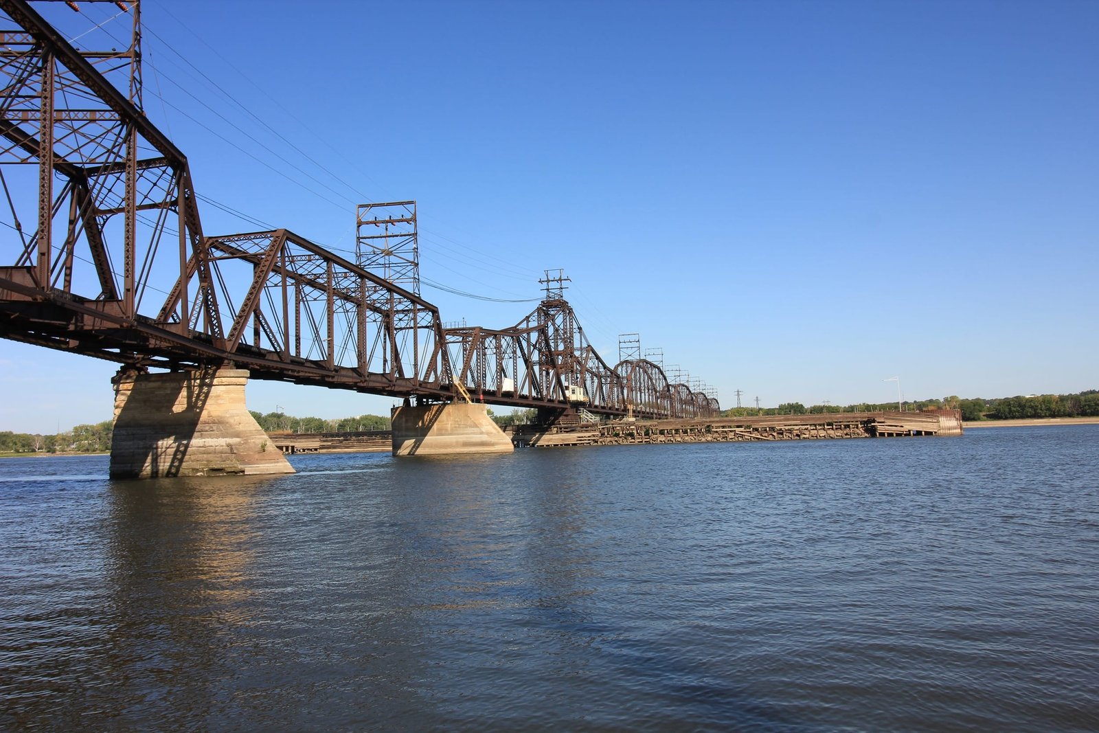
Located downstream of the Centennial Bridge between Davenport and Rock Island, this attractive through truss swing bridge carries the former Davenport, Rock Island & North Western Railway across the Mississippi River. In early 1885, a group of quad cities businessmen formed the Davenport & Rock Island Bridge Company, and obtained approval from Congress to construct a new railroad bridge over the Mississippi River. Limited surveys were completed, but work was generally stalled during the late 1880s and early 1890s. In 1895, the project was taken over by F.P. Blair, a businessman from St. Paul, Minnesota. After funding was secured, contracts were awarded and an engineer selected for the project in 1896. Charles F. Loweth was selected to design the structure and oversee the construction. Loweth was a prominent bridge engineer, who had constructed a number of large and complex bridges over the Mississippi River. A contract for the substructure was awarded to Charles Stone, a stonemason from St. Paul; and a contract for the steel superstructure was awarded to the Phoenix Bridge Company.
The new bridge would connect to the Chicago, Rock Island & Pacific Railway on both Iowa and Illinois sides, and to the Chicago, Burlington & Quincy Railroad on the Illinois shore. Because of how close the railroads were to the Mississippi River, the crossing would be required to use a curved alignment. The crossing would consist of three bridges, including a main truss bridge across the river, a short through plate girder bridge on the Illinois approach and a large deck plate girder bridge on the Iowa approach. Actual work on the bridge started in April 1896, starting with the construction of the Illinois approaches. Financial difficulties paused the work through 1896, and work resumed again in September of that year. Due to financial conditions at the time, work was halted a second time in 1896. A new contract for the substructures was awarded, and construction again was begun in September 1897. Work rapidly progressed after the last stoppage, and the bridge was constructed with minimal difficulty. In 1899, the bridge officially opened to traffic. The bridge was nicknamed the "Crescent Bridge", due to the semicircular shape of the alignment of the bridge and approached. Originally, the main bridge and north bridge were connected by a 52-foot deck plate girder and a timber pile trestle. In 1905, the bridge received its only major alteration, when the 52-foot span and trestle approach were removed, and a new 85-foot deck plate girder span installed on a concrete abutment. Wisconsin Bridge & Iron Company fabricated the deck girder, while the abutment was constructed by forces of the Milwaukee Road.
Currently, the bridge consists of a 442-foot swing span, which utilizes a rim bearing design and a hybrid truss design. Three Pratt through truss spans approach the swing span on the south, and four Pennsylvania through trusses and a deck plate girder span approach the bridge on the north side. Except for the north abutment, all substructures are constructed of stone. Most of the stone consists of Anamosa Limestone, quarried at Stone City, Iowa. The starlings and ice breakers are constructed of blue granite, quarried at St. Cloud, Minnesota. This different stone was used, as it is significantly harder than the limestone. The swing span (span #4) utilizes two 210-foot halves (leafs), which are connected over a pivot pier by a 20-foot wide tower. Each leaf consists of a 7-panel, pin-connected span, which utilizes a combination of Pratt and Baltimore through truss designs. The ends of each leaf contain a traditional Pratt design, while the inner portions of the leaves utilize a Baltimore design. Both halves use laced endposts, a built-up beam for the lower chord and a lattice portal with a decorative heel bracing. The swing span is powered by an electric motor, which is fed using power lines affixed to the top of the structure. The swing span utilizes a turning mechanism design which was standard for the Milwaukee Road, but varied from most railroads. At the end of the span, an end lift shoe consisting of cylinders allows the bridge to freely move up and down, or rotationally. In closed position, this shoe acts as a rocker bearing, absorbing small expansions and contractions. A shaft running longitudinally under the bridge carried power from the motor to the end shoes. The pivot mechanism on this bridge utilizes a rim-bearing design, where a drum constructed of a plate girder is set on a circular track of wheels, which carries the bridges entire weight. A pin at the center of the track maintains the proper alignment of the bridge. A series of radial plate girders extend from the center of the track to the drum girder. The main disadvantage of this design is the bridge must be constructed nearly flawlessly to avoid shifting.
The south approach (spans #1-3) consists of three 200-foot, 7-panel, pin-connected Pratt through truss spans, set on a 6-degree curve. These spans all use laced endposts, a combination of built-up beams and eyebars for the lower chord, and a lattice style portal with decorative heel bracing. To accommodate the significant curvature, the southern two of these spans utilize a slight skew and wider design. The first span immediately north of the swing span (span #5) consists of a 361-foot, 12-panel, pin-connected Pennsylvania through truss span, while the remaining truss spans (spans #6-8) consist of 300-foot, 10-panel versions of the same design. The Pennsylvania trusses all use laced endposts, a combination of built-up beams and eyebars for the lower chord, and an X-frame portal bracing with decorative heel bracing. In addition, the Pennsylvania spans all have an adjustable lower lateral bracing, a design that was rarely used when this bridge was constructed. An 85-foot deck plate girder has been installed on the north end (span #9), which uses a standard design. All truss spans use a traditionally composed floor, which consists of steel girders for floor beams and the stringers.
It was not uncommon for large swing spans to use a hybrid truss design. Due to the size of the center tower, these spans could not be constructed with a flat top chord. Instead of using a high top chord throughout, it was more economical to use a top chord which varied in height. Because of this, multiple truss designs were often required. Typically, single intersection truss designs were used at the ends of each leaf, while the portions of each half near the center tower often used a Baltimore design. While more rigorous to design, this design came at a significant cost savings, both for steel material and for substructures, as the dead weight of the structure was significantly reduced.
Originally, the main bridge was approached by separate bridges on each side. The Iowa side structure consisted of seven 71-foot deck plate girder spans, set onto concrete substructures. An additional wye track was added between the Iowa end of the main bridge and the Rock Island tracks heading south prior to the 1930s, and used an unknown structure, likely a girder bridge. As the river was improved, these overflow structures were no longer required. The Illinois structure consisted of a curved through plate girder bridge, set onto steel towers and concrete abutments. Aerial imagery indicates that the Illinois structure was filled and removed between 1976 and 1984, while the Iowa approaches were filled and removed between 1986 and 1994.
Since the initial construction, the bridge has seen few alterations. It appears the original roller bearings for the swing span were replaced, although the original drum, wheels and gears appear intact. Pier #3 has been encased in concrete, likely due to failing stonework. In addition, the original fenders protecting the pivot pier have been repaired and upgraded. Few repairs or strengthening have been made to the bridge, leaving the bridge in nearly its original appearance. Overall, the bridge appears to be in fair to good condition, with only minor deterioration noted. Most of the visible deterioration is concentrated in the substructures, and is largely composed of minor stone cracking. The author has ranked this bridge as being highly significant, as it is a well preserved example of a Mississippi River swing bridge.
Citations
| Builder and build date | Engineering News; Volume 43, Issue 2 |
| Builder and build date (north approach) | Wisconsin Bridge & Iron Company plaque |
| Railroad History Citation | ICC Valuation Information, Compiled by Richard S. Steele |