


Click the photo to view the full-size version
| Name | CPKC Kinnickinnic River Bridge Chicago, Milwaukee & St. Paul Railway Bridge #A-314 |
| Built By | Chicago, Milwaukee & St. Paul Railway |
| Currently Owned By | Canadian Pacific Kansas City Limited |
| Superstructure Contractor | American Bridge Company of New York |
| Design Engineers | Charles Frederick Loweth (Chief Engineer/Superintendent of Bridges and Buildings) J.H. Prior (Assistant Engineer) |
| Length | 256 Feet Total, 196 Foot Main Span |
| Width | 2 Tracks |
| Height Above Ground | 15 Feet (Estimated) |
| Superstructure Design | Warren Through Truss and Deck Plate Girder |
| Substructure Design | Concrete |
| Date Built | 1908, Approach Replaced c. 2000 |
| Traffic Count | 40 Trains/Day (Estimated) |
| Current Status | In Use |
| Chicago, Milwaukee & St. Paul Railway Bridge Number | A-314 |
| Significance | High Significance |
| Documentation Date | 6/13/2014; 5/7/2022 |
In 1872, the Chicago, Milwaukee & St. Paul Railway (Milwaukee Road) constructed 45 miles of new railroad, extending from the Chicago & North Western Railway mainline at Western Avenue in Chicago to the Illinois/Wisconsin State Line near Gurnee, Illinois. The Wisconsin Union Railroad started an additional 37 miles to Milwaukee in 1872, with the Milwaukee Road completing the line in 1873. The Wisconsin Union became part of the Milwaukee & St. Paul Railway in 1872; which became part of the Chicago, Milwaukee & St. Paul Railway in 1874. The Milwaukee Road was beginning to acquire and construct a large number of railroad lines, particularly in Wisconsin. This line served as an arterial mainline for the railroad, connecting terminals at Milwaukee to terminals at Chicago. Due to heavy traffic, the entire line was double tracked between 1892 and 1893. In the late 19th Century, railroad traffic had become a significant
safety hazard for the City of Chicago. A solution was devised to
elevate the railroad tracks throughout the city, placing the railroads
upon embankments and constructing subways at each street. The line between Western Avenue and Irving Park Road would be elevated between 1899 and 1902. In Milwaukee, the tracks would be elevated in 1916. Further track elevation would be completed between 1927 and 1929 from Irving Park Road to Elston Avenue.
By the 20th Century, the Milwaukee Road had become a prominent railroad
in the United States, operating a network of railroad lines primarily in
the Midwest. The Milwaukee Road was often in financial trouble,
especially after the
costly Pacific Extension was completed in 1909. In 1925, the company
declared bankruptcy, and reorganized as the Chicago, Milwaukee, St. Paul
and Pacific Railroad in 1928. This line continued to serve as the principal mainline of the company, extending to the Pacific Ocean. By 1985, a suitor for the Milwaukee Road was being sought, and the Soo
Line Railroad, controlled by Canadian Pacific Railway (CP) purchased the
Milwaukee Road in 1986. CP merged with
Kansas City Southern
Railway in 2023 to form CPKC. Today, CPKC operates this line as the C&M Subdivision. In addition, Metra operates the Milwaukee District North commuter service between Western Avenue and Rondout.
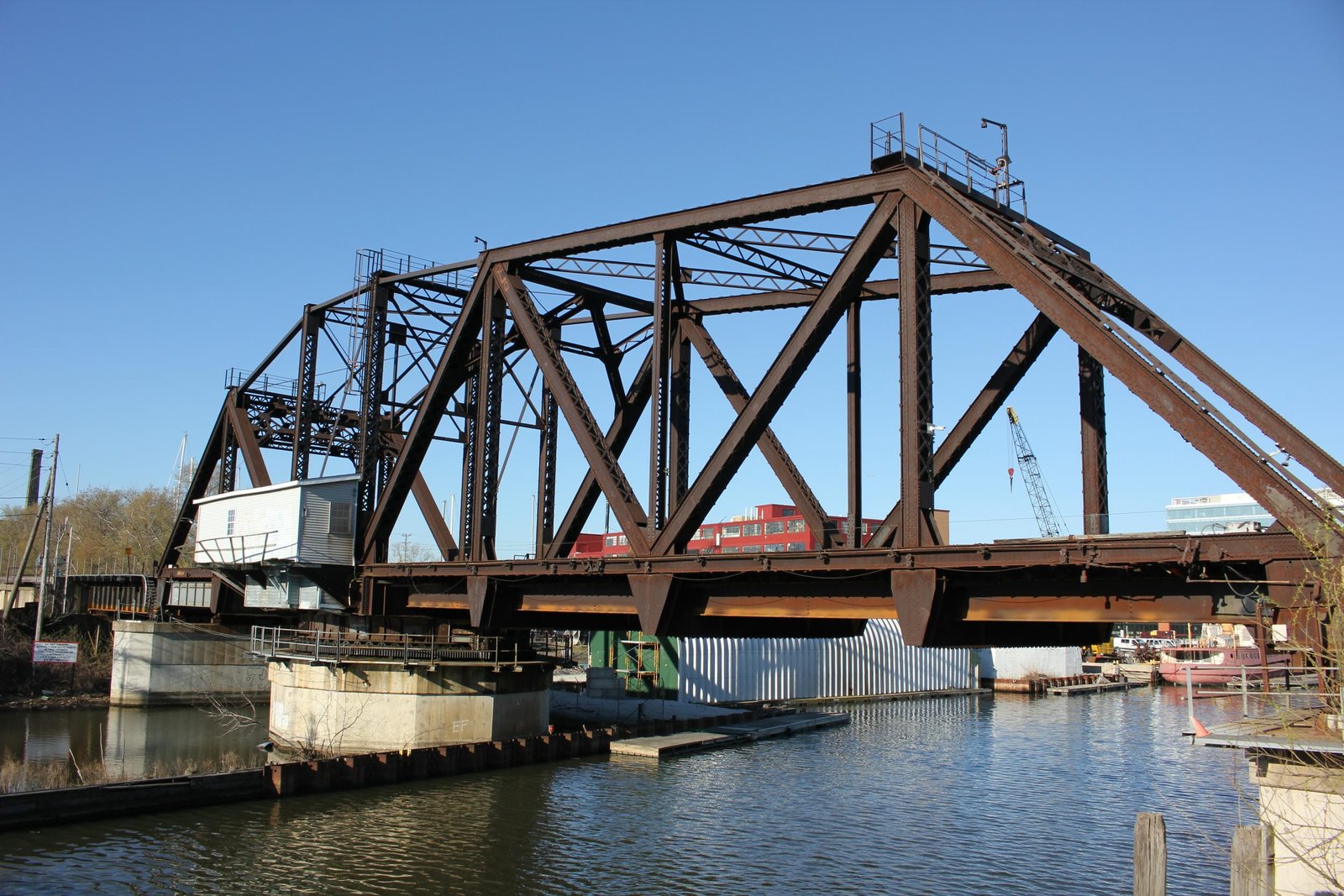
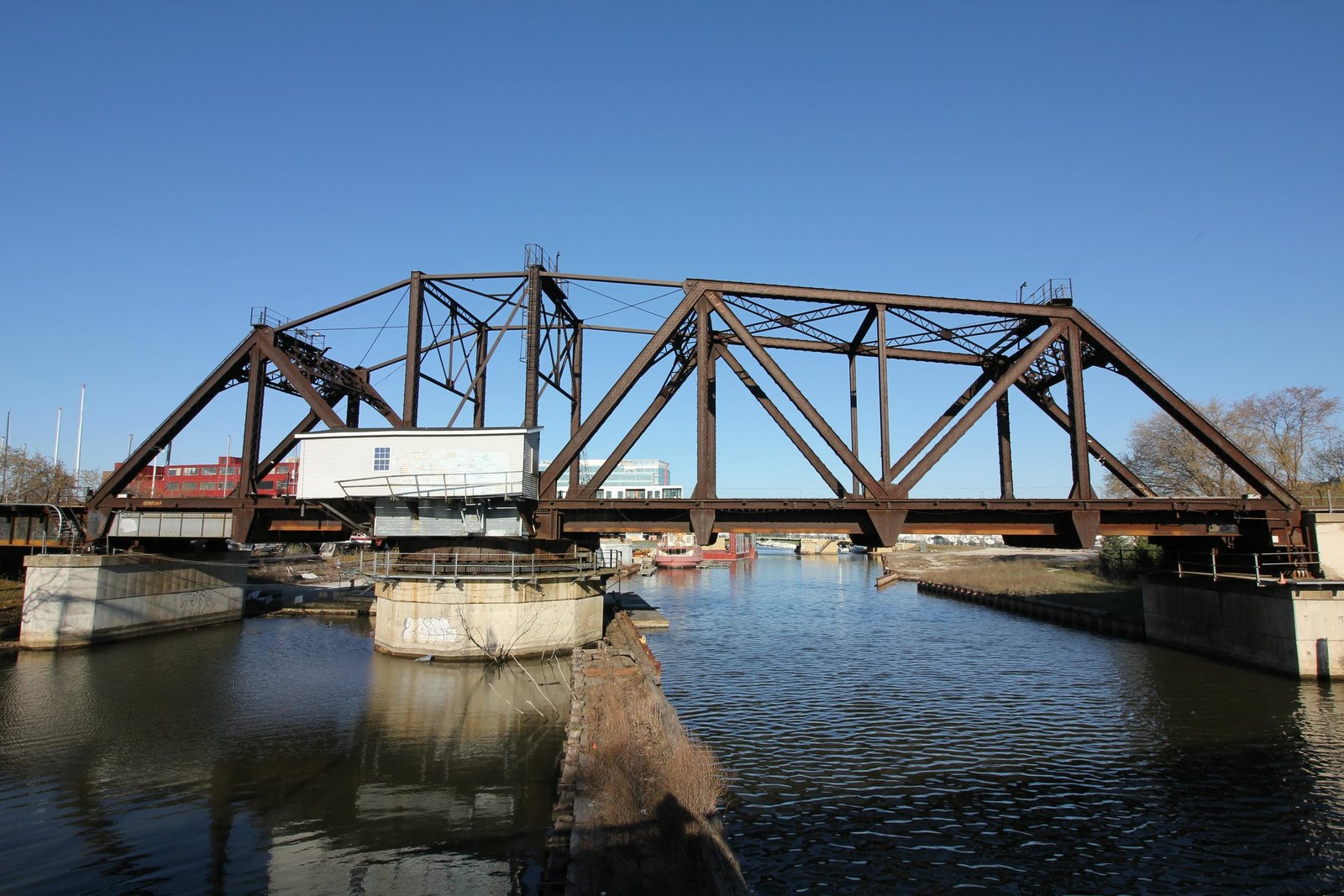
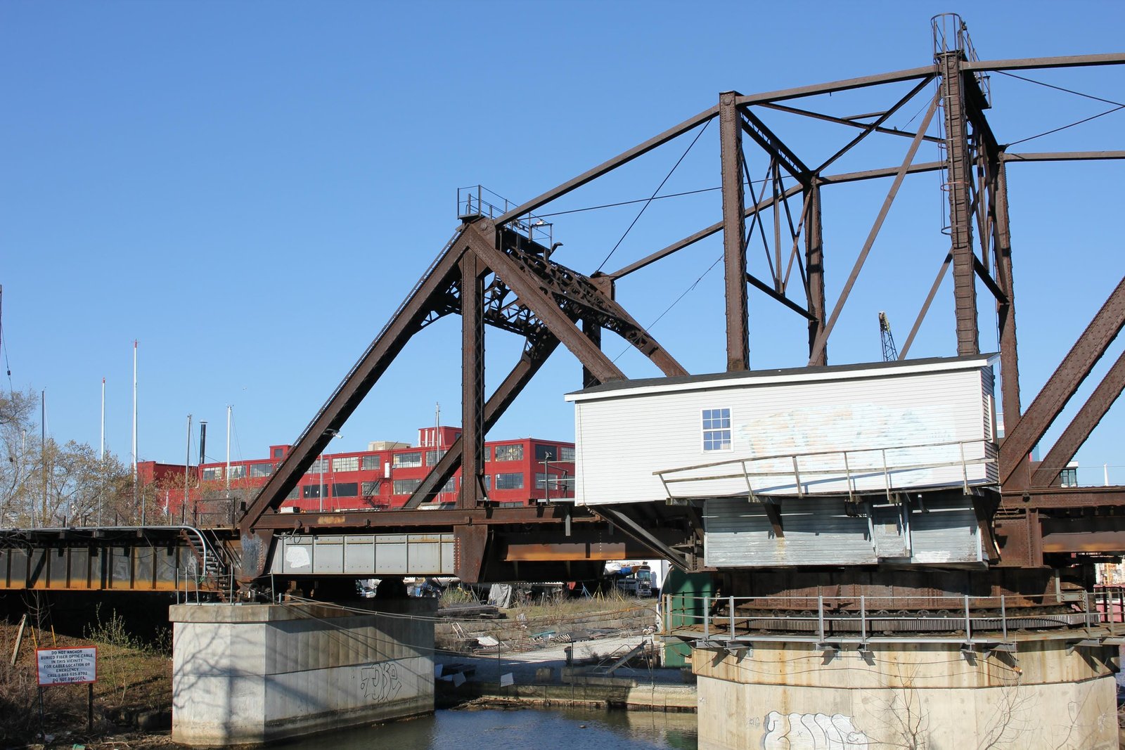
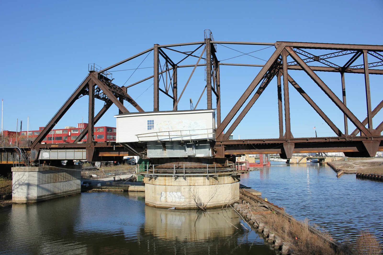
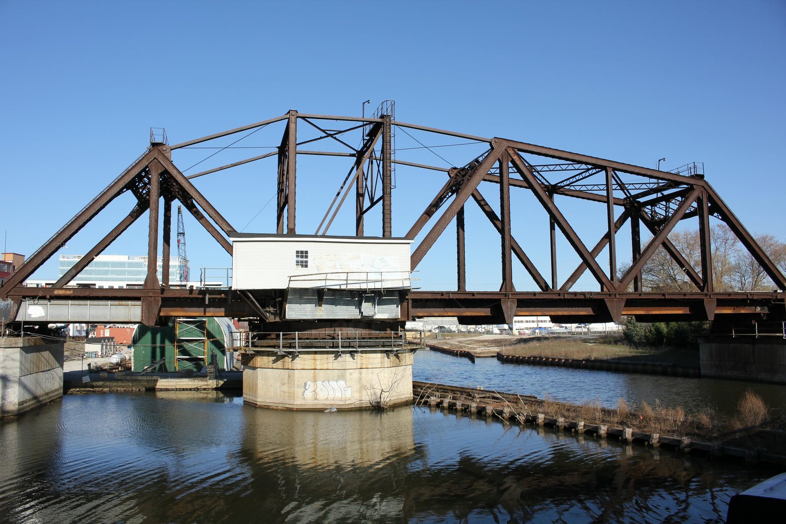
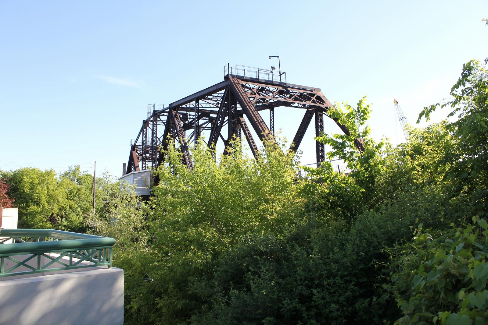
Located alongside Kinnickinnic Avenue in Milwaukee, this unique counterbalanced through truss swing bridge carries the former Chicago, Milwaukee, St. Paul & Pacific Railroad (Milwaukee Road) over the Kinnickinnic River. The first bridge at this location was likely a single track wooden truss bridge, constructed when the line was first built. It is unknown if this bridge was upgraded during the 1870s. In 1881, the bridge was replaced by a 172-foot symmetrical rim-bearing swing span, fabricated by an unknown contractor. This span was likely lightly constructed, using a pin-connected Pratt design lightly constructed members. By the turn of the 20th Century, the 1880s-era swing bridges in Milwaukee had become too light for traffic, and the Milwaukee Road began making plans to replace the structures. Because this structure served a critical mainline of the Milwaukee Road, it was paramount to keep the old bridge in service while a new bridge was constructed. The chosen design for the replacement bridge was a counterbalanced swing bridge. It is likely that this design was chosen due to its simplicity, economical nature and minimal impacts to adjacent properties. It is also possible that the design was chosen to limit interference to railroad traffic while constructing the bridge. Counterbalanced swing spans had been constructed at several locations throughout the Milwaukee Road system, and the chosen design used a 196-foot Warren through truss design.
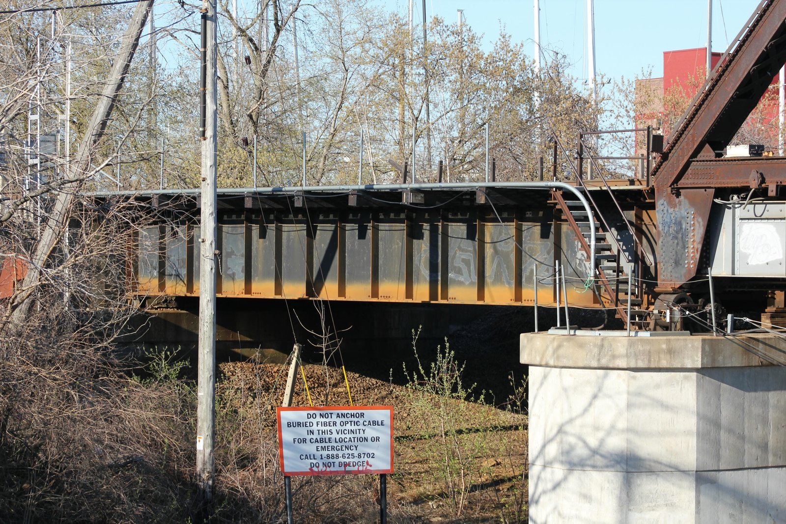
The construction process for this bridge is not well documented. It is likely that a similar arrangement to other swing spans in Milwaukee was used to construct the bridge. This arrangement involved removing half of the existing bridge, placing the remaining half on piles and constructing a temporary timber bridge. During this time, half of the new bridge could be constructed, before the staging removed the other half of the bridge and completed the structure. In addition to constructing all new substructures, a 60-foot deck plate girder span was installed on the south end of the bridge. It is believed that all work on the bridge was done by labor employed by the Milwaukee Road Bridge & Building Department; which maintained a highly skilled group of laborers capable of quickly and efficiently completing complex construction. American Bridge Company reportedly fabricated the superstructure, and the new bridge was designed under the direction of J.H. Prior; Assistant Engineer and Charles F. Loweth; Chief Engineer and Superintendent of Bridges and Buildings. The most recent alterations to the bridge came in approximately 2000, when the original south approach was replaced by modern span of the same design, and the truss span saw a number of alterations.
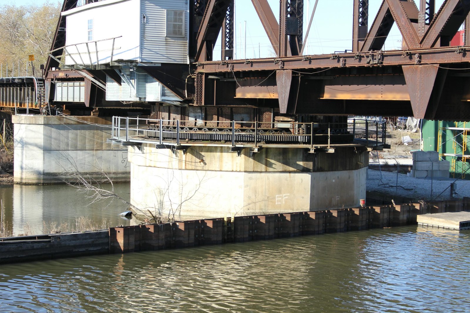
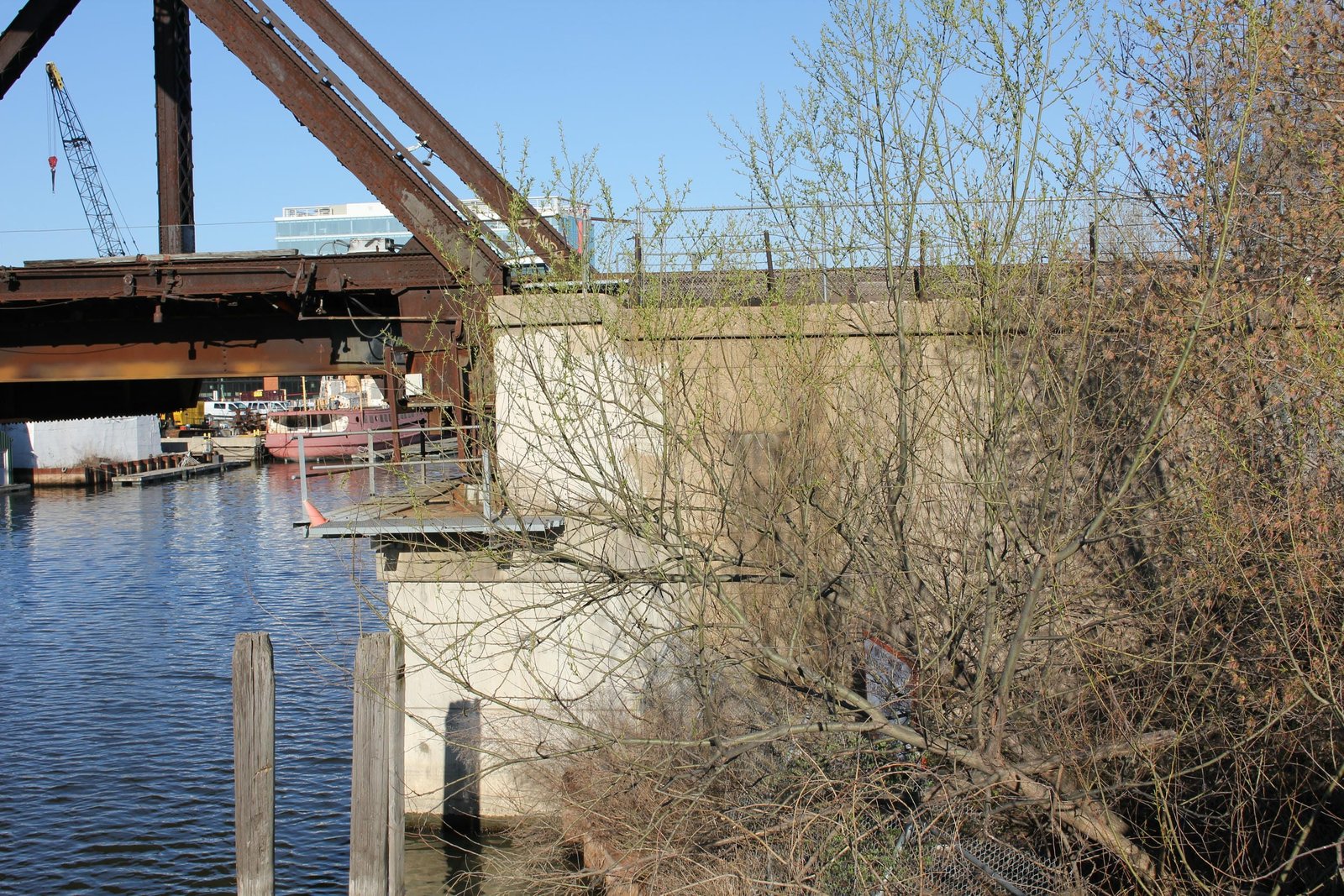
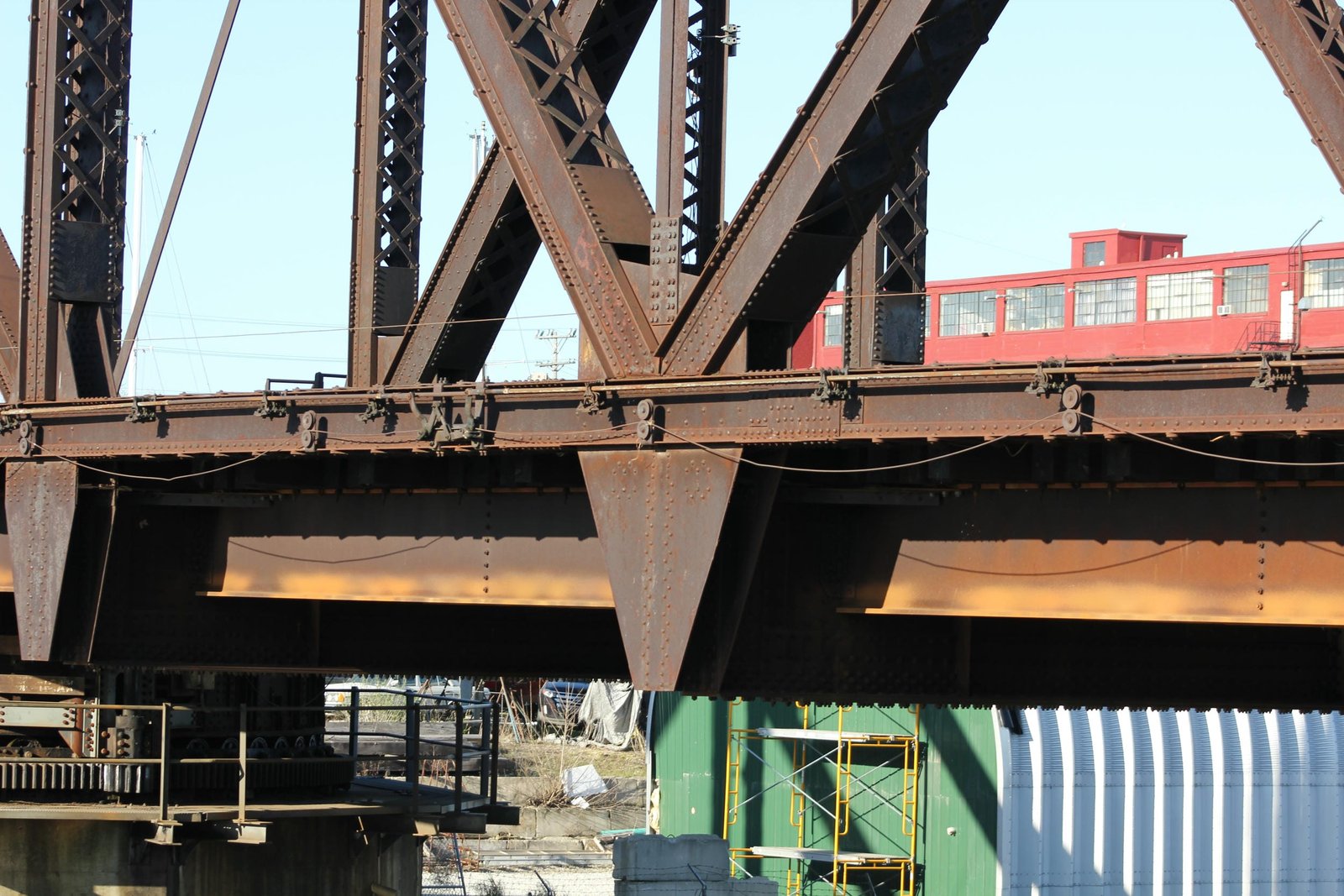
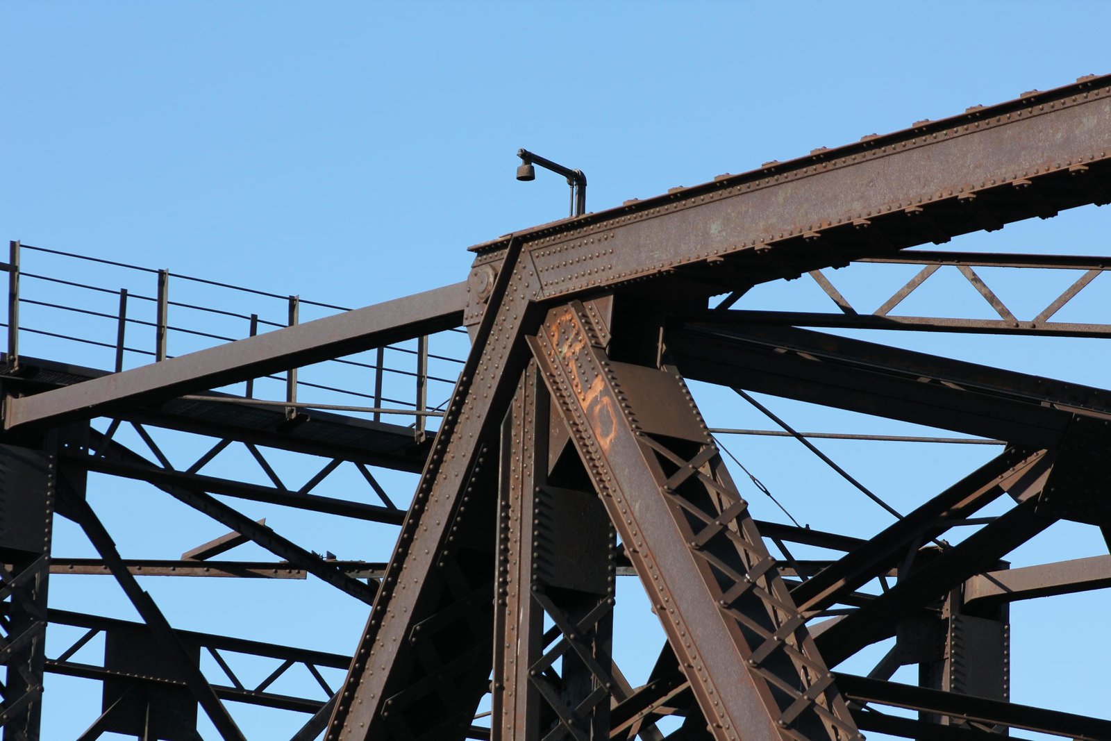
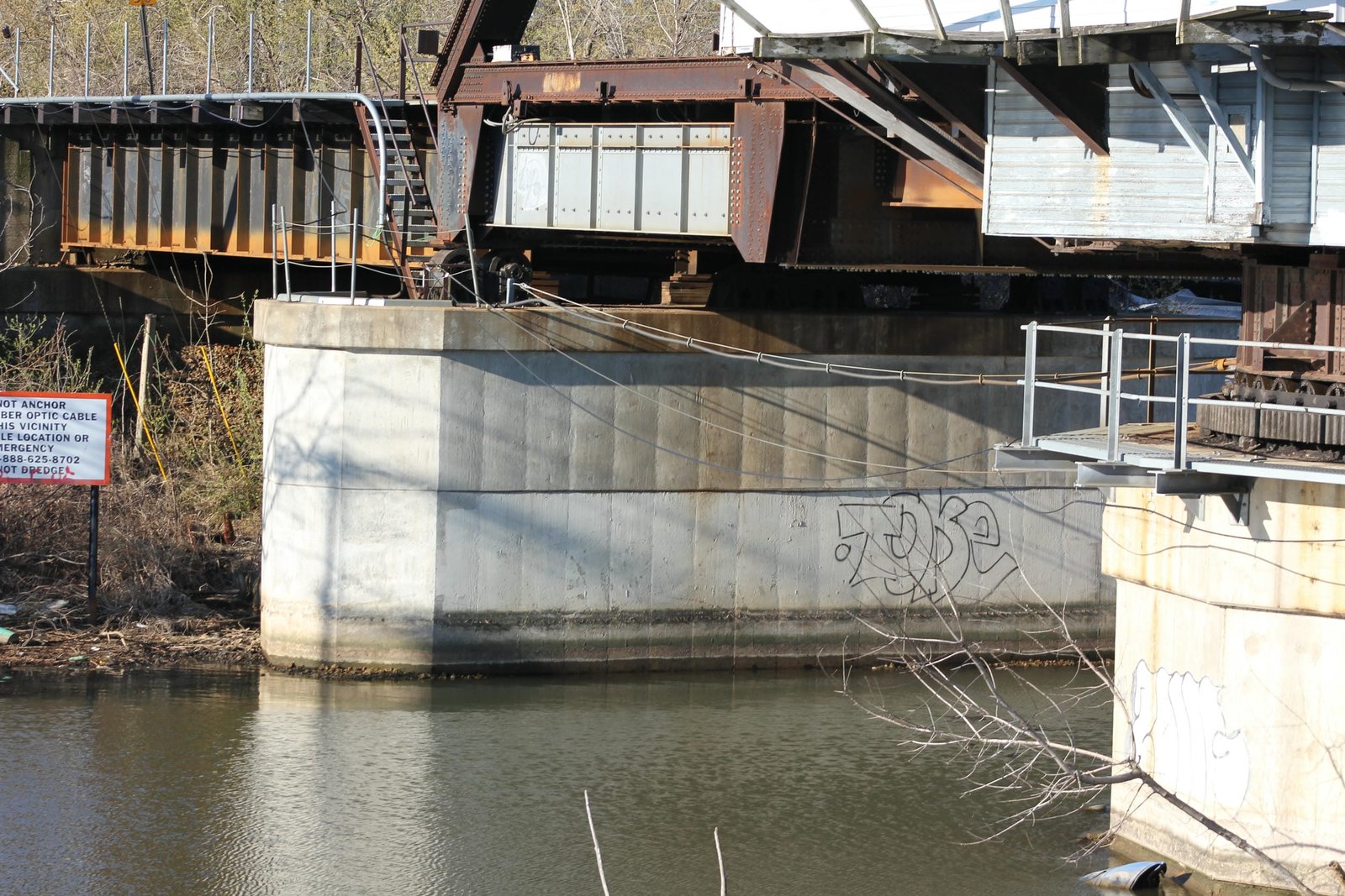
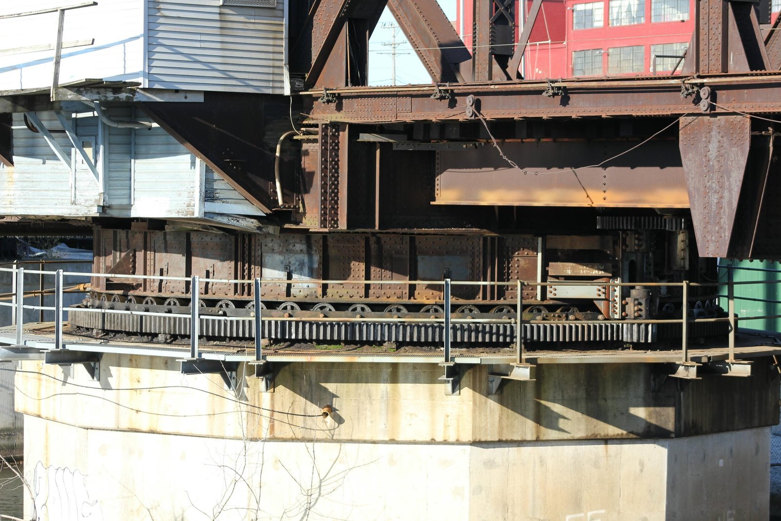
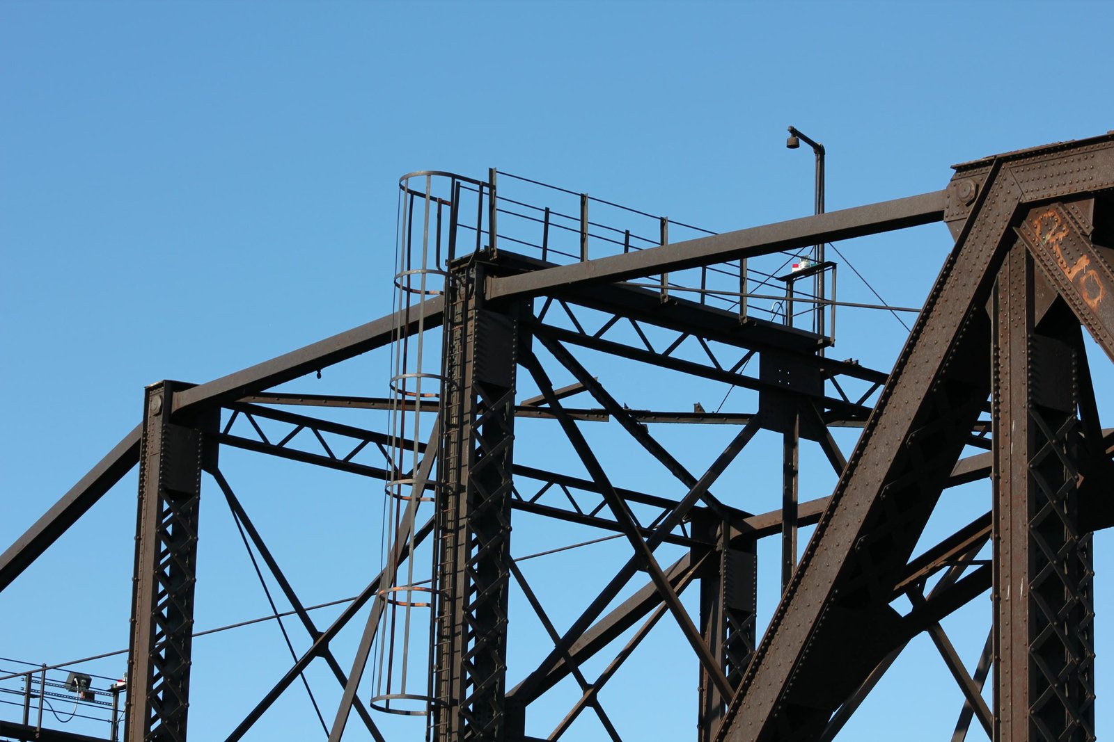
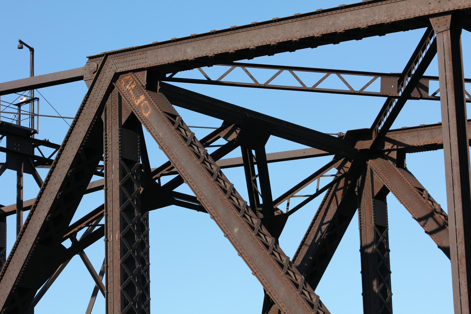
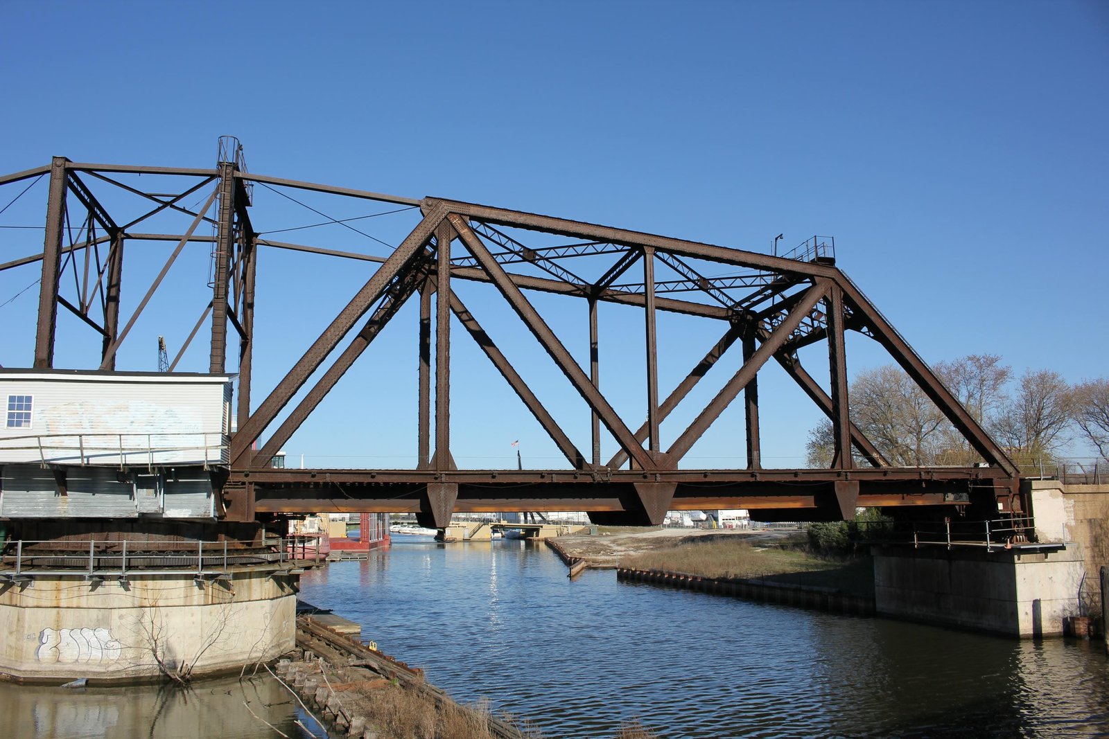
Currently, the bridge consists of a 196-foot, riveted counterbalanced Warren through truss swing span, approached by a 60-foot deck plate girder span on the south end. The entire bridge is set onto concrete substructures, which are founded on timber piles. The swing span is divided into three unique sections: a 112-foot, 4-panel north arm; a 21-foot, 1-panel center section, and a 63-foot, 2-panel south (counterweight) arm. The swing span uses a rim-bearing design, where the superstructure is set onto a steel drum, which rotates about a roller nest and is driven by a gear system. The center pier is shaped as a dodecagon, which is set onto dozens of timber piles driven deep into the riverbed. The south pier uses a standard diamond shape, while the abutments both use an elongated U-shape, typical of many Milwaukee Road bridges. The Milwaukee Road constructed two other counterbalanced swing spans in Milwaukee, with the Menomonee River Bridge completed in early 1904 and the Burnham Canal Bridge completed in 1906-07. This bridge uses a more refined design than the other two spans, with many of the components constructed much heavier. Despite this, a number of unique design features are found throughout the truss span. Some of these features include a variety of types of built-up beams, unusual bracing and unique connections.
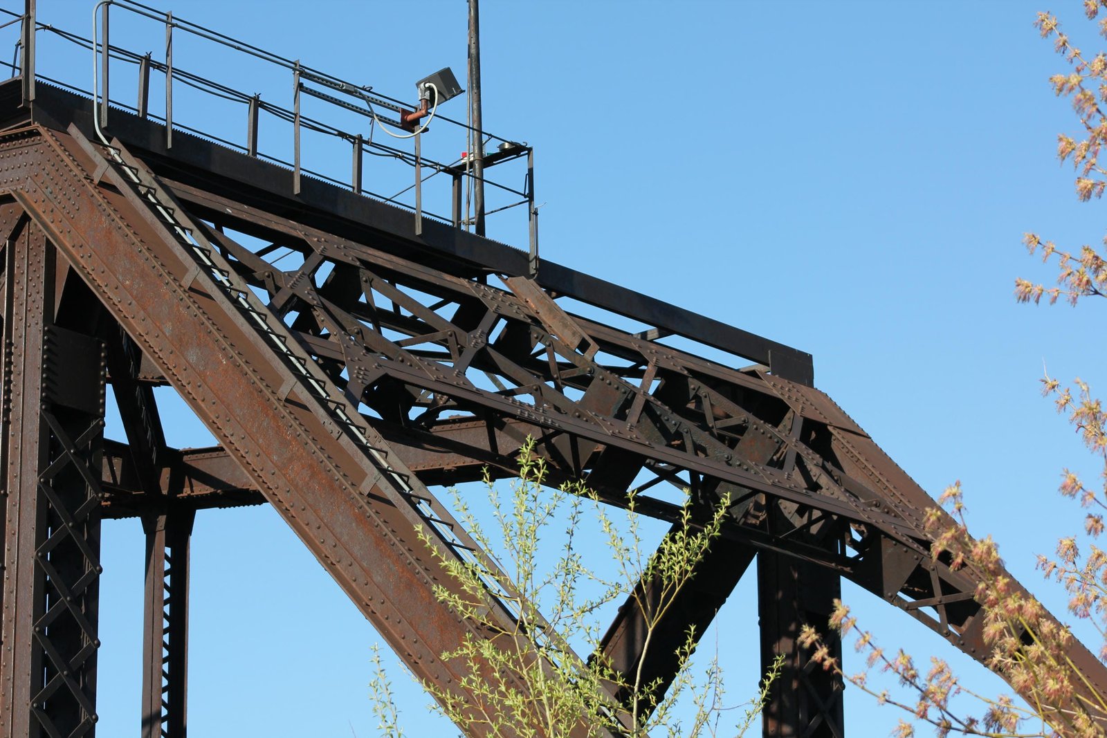
The top chord of both the north and south arms is constructed of built-up beams, connected by X-lacing on both sides. At the center panel and innermost panels of each arm, the top chord is constructed thick square eyebars. Both the outer and inner endposts of both arms are constructed of a built-up beam, connected by X-lacing on the interior and a solid plate on the exterior. The bottom chords throughout the structure are also constructed of built-up beams, with X-lacing on the top and bottom. All vertical members are constructed of built-up beams of different sizes, all of which use extensive X-lacing. With the exception of the diagonal member across the center section, the diagonal members are also composed of heavily built-up beams with extensive X-lacing. The center section is surrounded by vertical members on all four quadrants, which are connected by a deep sway brace and a diagonal eyebar which runs from the top of the north member to the bottom of the south member. This bridge is unique, as there are dedicated endposts on either side of the center section, clearly defining the two arms. The diagonal member at the center section is connected by pinned connections on either end, as are the eyebars forming the top chord for the center section and adjacent panels. The pinned connections are located in large gusset plates, which contain a riveted connection on the opposite side of the pinned connection. The floor uses a standard design, with plate girder floorbeams at the panel points and I-beam stringers to support the tracks. While the floorbeams appear original to the structure, the stringers were constructed in approximately 2000 to replace the original plate girder stringers. Other minor repairs were made at this time, including replacing some rivets with high-strength bolts.
The counterweight system uses a more refined design than previous counterbalanced through truss swing spans. Instead of the counterweight being placed above the tracks on an additional arm, the counterweight is constructed of concrete and iron placed underneath the track at the southernmost panel of the south arm. While requiring a greater weight, this configuration eliminated the need for an over-the-track design, and allowed for a more appealing design. The counterweight appears to have been heavily modified during the c. 2000 repairs, with new steel plates on the exterior of the counterweight section. It is likely that the original concrete may have been repaired or replaced at this time. The portal bracing at both the inner and outer endposts uses a similar double intersection lattice design, constructed out of X-laced beams. At the vertical members on either side of the center section, the sway bracing consists of a V-laced strut and a deep double intersection lattice design. Throughout the rest of the bridge, the sway bracing consists of V-laced struts. The upper lateral bracing at the arms is composed of lightly V-laced beams, while it is composed of steel rods at the center section and adjacent panels of each arm. The lower lateral bracing is likely composed of steel bars, typical for truss bridges of this era.
This bridge varies from both traditional swing bridges and past Milwaukee Road bridges in the lifting, locking and rotating mechanisms. When operating, the rail lifts at the end of the bridge are first operated. These mechanisms lift the rail, and allow the bridge to swing freely. Next, the locking mechanism is lifted, and the span is rotated slightly, before the operator engages the motor of the rotating mechanism. The operator then stops the rotation by cutting power to the motor or by applying a brake. Many traditional swing spans use wedges driven at the end to lift the span after the locking mechanism was disengaged. Previous Milwaukee Road bridges used a cam-shaped bearing block to lift the bridge. This bridge appears to use a design consisting of two different sized wheels, which serve as both a lifting mechanism and a bearing block. These are likely operated by a shaft which runs underneath the span. The pivot mechanism on this bridge utilizes a rim-bearing design, where a drum constructed of plate girders rides on a circular track of rollers, which carries the bridges entire weight. A pin at the center of the track maintains the proper alignment of the bridge. The drum constructed for this bridge is a two-part structure. Two separate square drums are located offset of the center of the center panel, and one large transverse girder is located in the exact center. This helps evenly spread the weight of the bridge, and provides room for the machinery. The top portion of the drum is placed onto a lower drum, which is constructed of plate girders. This drum is placed directly onto the roller nest, and is supported from the center pin by use of radial girders. Machinery for operating the bridge appears to be located within the center pier, and is controlled from a machinery house located on the east side of the bridge. Because the river remains navigable, the swing span still operates when needed.
Counterbalanced, or "bobtail" spans, were infrequently used by railroads. These spans provided most of the drawbacks of a symmetrical swing span, with additional weaknesses in the counterbalanced design. Counterbalanced spans required precise calculations, additional costs and often required difficult engineering. This type of swing span utilizes a large counterweight on one arm (the counterweight arm), which offsets the longer length of the main arm of the span. Due to the different lengths, a counterbalanced swing span cannot rotate a full 360 degrees, and instead must come to a stop and rotate the opposite direction during opening and closing operations. While the additional time needed to stop and restart amounts to mere minutes, the additional time was often considered inadequate for railroads. The Milwaukee Road designed and implemented a number of counterbalanced swing spans throughout the system, constructing the most known spans of any railroad in the United States. Of these spans, three were constructed in Milwaukee, including additional spans across Burnham Canal and the Menomonee River. Because the Milwaukee Road designed and constructed so many counterbalanced swing spans, the design was altered as needed, using both plate girder and truss designs. Many Milwaukee Road designed counterbalanced spans remain intact today.
In the early 20th Century, many railroads were transitioning from using pin-connected Pratt truss spans to riveted Warren truss spans. Riveted Warren spans provide a greater rigidity and strength, while maintaining a simple and economical design. Earlier counterbalanced swing spans constructed by the Milwaukee Road used either plate girder designs, such as Bridge #Z-6 or a Pratt truss design, such as Bridge #Z-2. This bridge uses a refined variation of a counterbalanced Warren through truss design. The other two counterbalanced bridges in Milwaukee were the first to use the Warren design in this application, and this bridge was followed by further refined structures at Bridge #J-0 in Chicago. At least one subsequent counterbalanced span returned to a Pratt design, possibly due to the length required. Since the initial construction, the bridge has seen a number of alterations, which are detailed above. Despite these alterations, the bridge retains excellent historic integrity, and is one of only a handful of counterbalanced swing spans ever constructed in the United States. Unfortunately, CPKC, the current owner of the three Milwaukee counterbalanced spans plans to replace the Burnham Canal bridge, possibly as soon as 2026. It is also possible that this bridge and the Menomonee River Bridge may also be replaced in later projects. Overall, the bridge appears to be in fair condition, with recent repairs hopefully extending the life of the bridge. The author has ranked this bridge as being highly significant, due to the unique and innovative design.
Citations
| Build date | Milwaukee Road Drawing Collection, located at the Milwaukee Road Archives at the Milwaukee Public Library |
| Builder | Reconnaissance Survey of Historic Railroad Bridges over Waterways in Milwaukee County, Wisconsin; May 2023 |
| Railroad History Citation | ICC Valuation Information, Compiled by Richard S. Steele |