

Click the photo to view the full-size version
| Name | CPKC Menomomee River Swing Bridge Chicago, Milwaukee & St. Paul Railway Bridge #A-316 1/2 |
| Built By | Chicago, Milwaukee & St. Paul Railway |
| Currently Owned By | Canadian Pacific Kansas City Limited |
| Superstructure Contractor | American Bridge Company of New York (Lassig Plant) Unknown (North Approach) |
| Design Engineers | Charles Frederick Loweth (Chief Engineer/Superintendent of Bridges and Buildings) James J. Harding (Assistant Engineer) |
| Length | 243 Feet Total; 203 Foot Main Span |
| Width | 2 Tracks |
| Height Above Ground | 15 Feet (Estimated) |
| Superstructure Design | Counterbalanced Warren Through Truss Swing Span and Deck Plate Girder |
| Substructure Design | Concrete |
| Date Built | 1904, North Approach Replaced c. 2000 |
| Traffic Count | 40 Trains/Day (Estimated) |
| Current Status | In Use |
| Chicago, Milwaukee & St. Paul Railway Bridge Number | A-316 1/2 |
| Significance | High Significance |
| Documentation Date | 6/13/2014; 5/7/2022 |
In 1872, the Chicago, Milwaukee & St. Paul Railway (Milwaukee Road) constructed 45 miles of new railroad, extending from the Chicago & North Western Railway mainline at Western Avenue in Chicago to the Illinois/Wisconsin State Line near Gurnee, Illinois. The Wisconsin Union Railroad started an additional 37 miles to Milwaukee in 1872, with the Milwaukee Road completing the line in 1873. The Wisconsin Union became part of the Milwaukee & St. Paul Railway in 1872; which became part of the Chicago, Milwaukee & St. Paul Railway in 1874. The Milwaukee Road was beginning to acquire and construct a large number of railroad lines, particularly in Wisconsin. This line served as an arterial mainline for the railroad, connecting terminals at Milwaukee to terminals at Chicago. Due to heavy traffic, the entire line was double tracked between 1892 and 1893. In the late 19th Century, railroad traffic had become a significant
safety hazard for the City of Chicago. A solution was devised to
elevate the railroad tracks throughout the city, placing the railroads
upon embankments and constructing subways at each street. The line between Western Avenue and Irving Park Road would be elevated between 1899 and 1902. In Milwaukee, the tracks would be elevated in 1916. Further track elevation would be completed between 1927 and 1929 from Irving Park Road to Elston Avenue.
By the 20th Century, the Milwaukee Road had become a prominent railroad
in the United States, operating a network of railroad lines primarily in
the Midwest. The Milwaukee Road was often in financial trouble,
especially after the
costly Pacific Extension was completed in 1909. In 1925, the company
declared bankruptcy, and reorganized as the Chicago, Milwaukee, St. Paul
and Pacific Railroad in 1928. This line continued to serve as the principal mainline of the company, extending to the Pacific Ocean. By 1985, a suitor for the Milwaukee Road was being sought, and the Soo
Line Railroad, controlled by Canadian Pacific Railway (CP) purchased the
Milwaukee Road in 1986. CP merged with
Kansas City Southern
Railway in 2023 to form CPKC. Today, CPKC operates this line as the C&M Subdivision. In addition, Metra operates the Milwaukee District North commuter service between Western Avenue and Rondout.
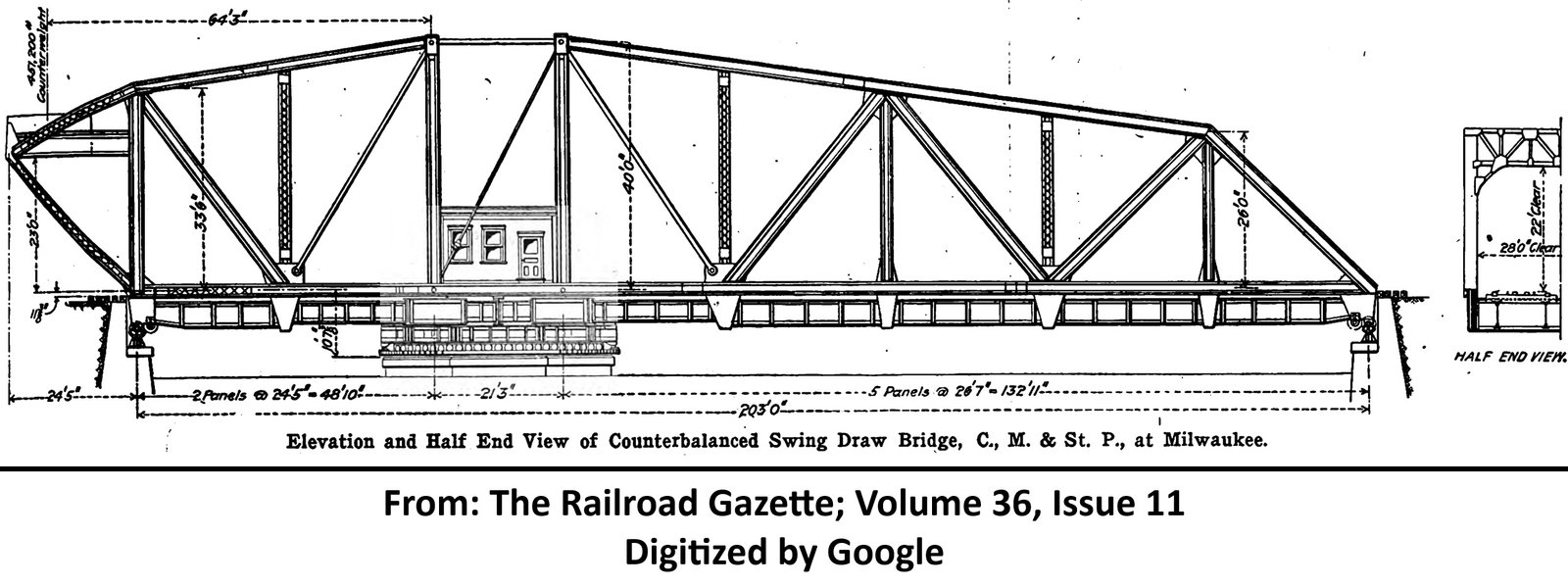
View historic articles discussing the construction of this bridge (digitalized by Google)
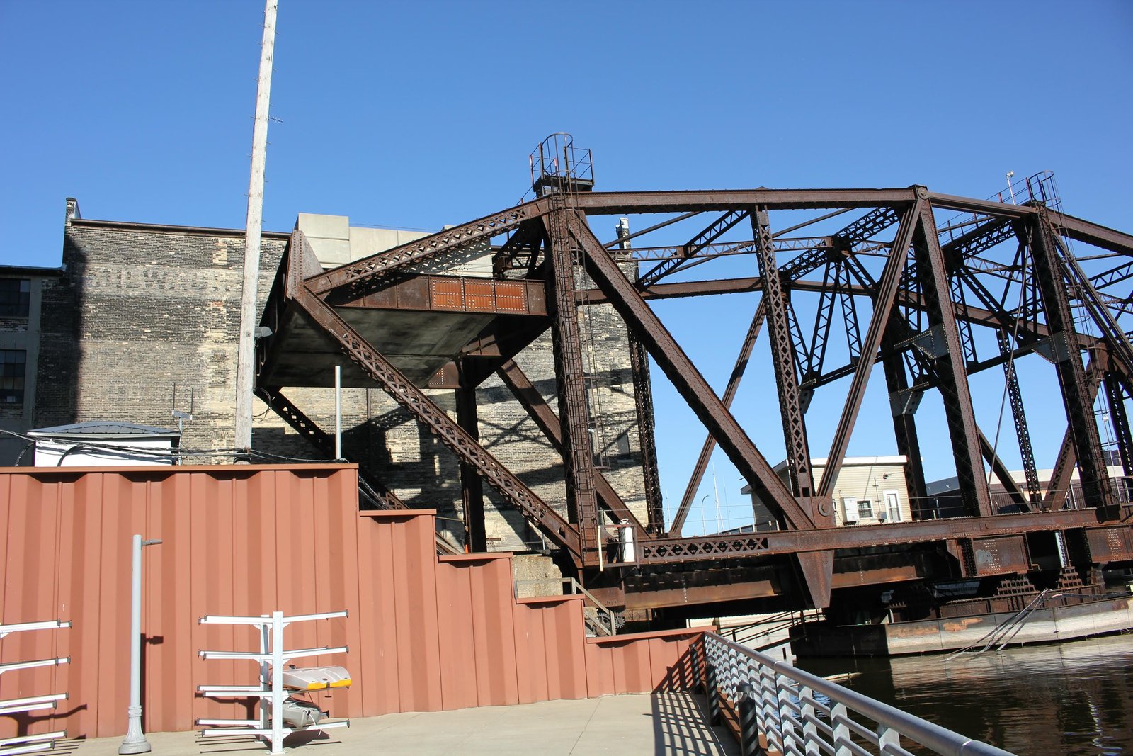
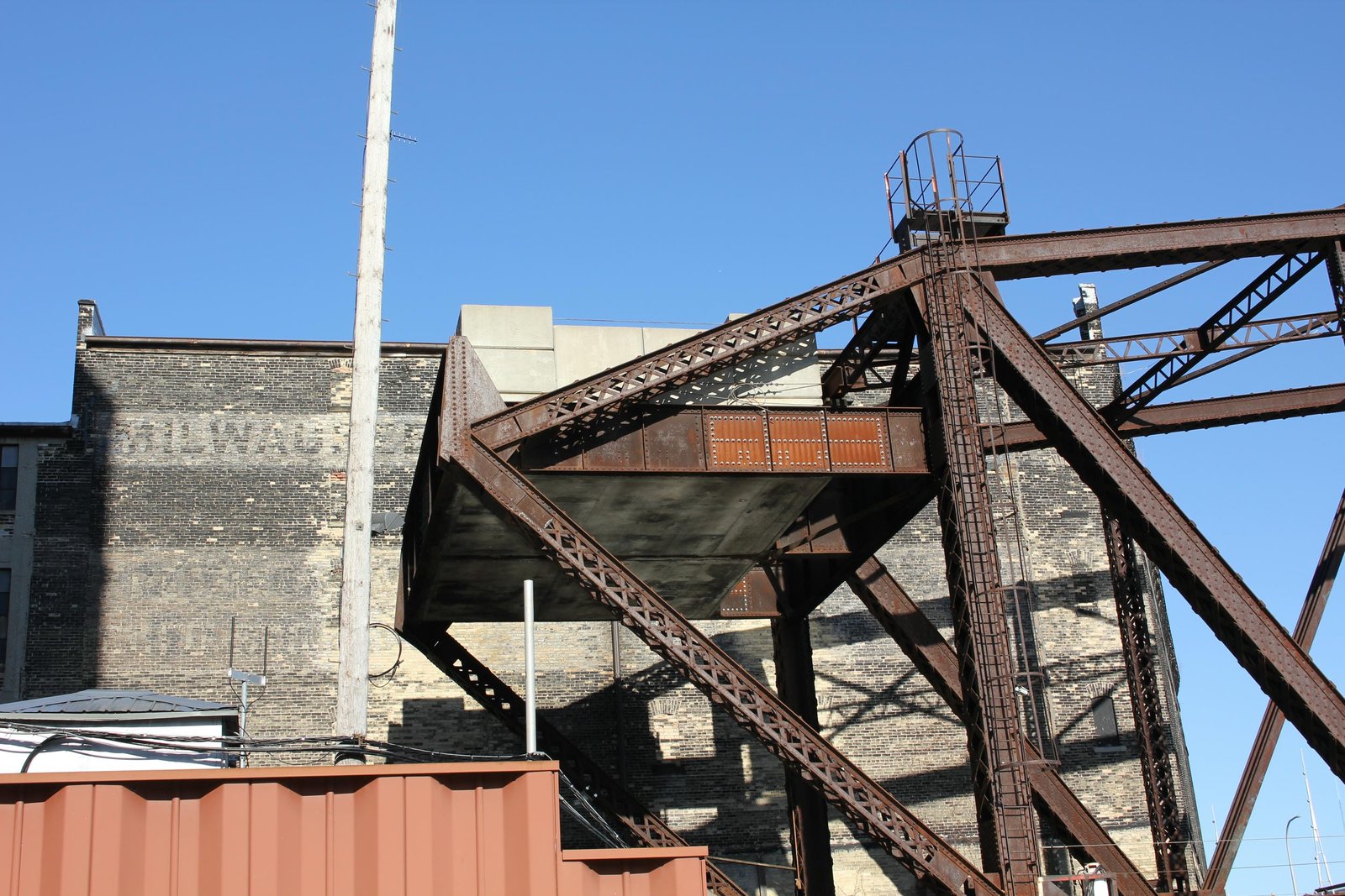
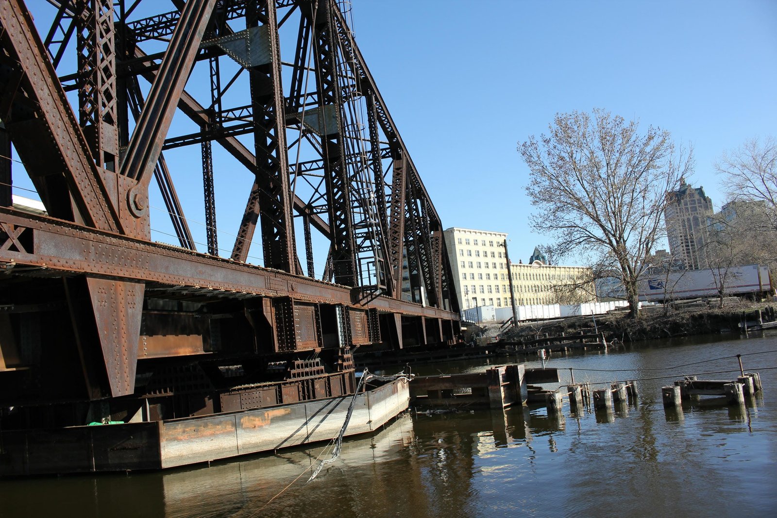
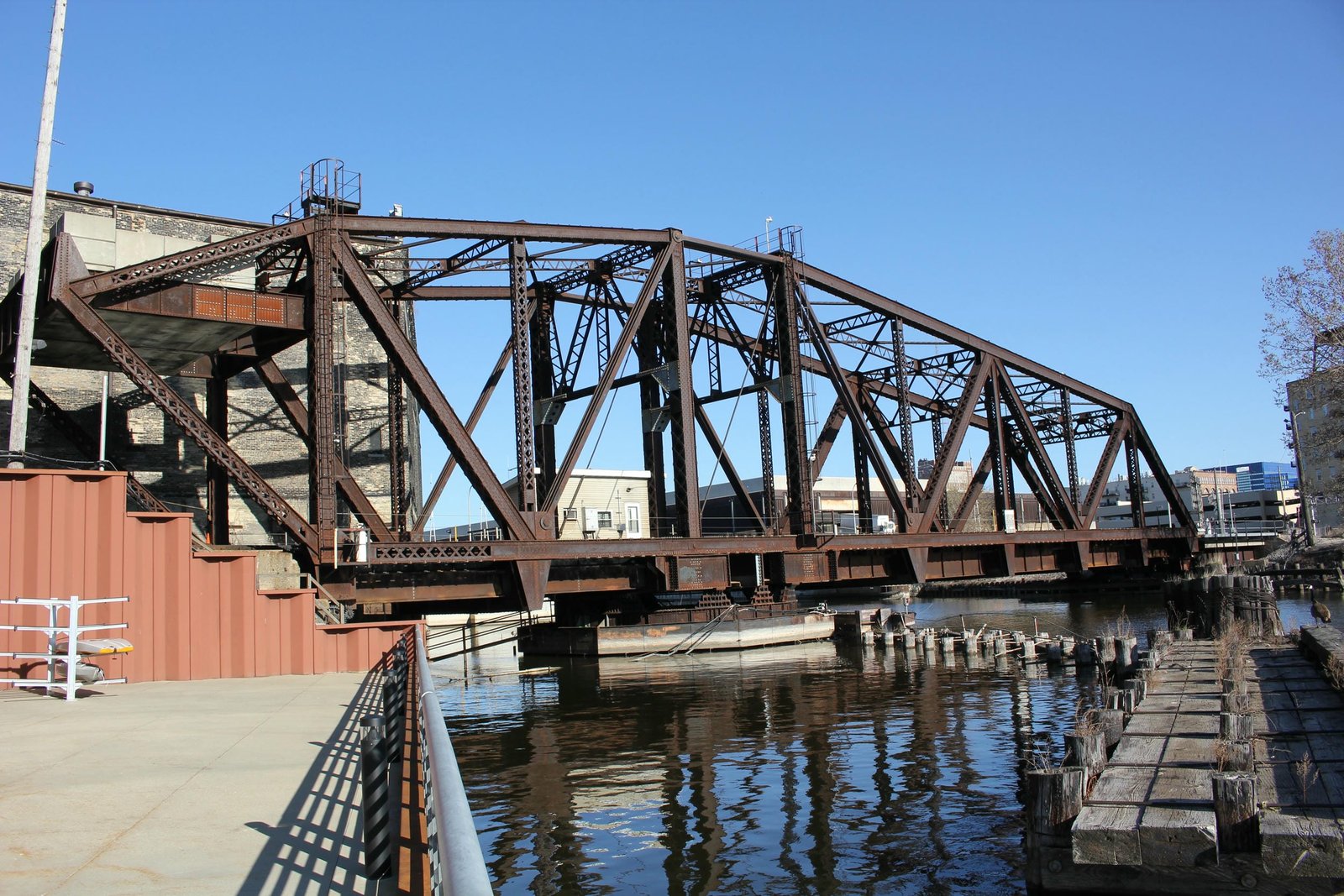
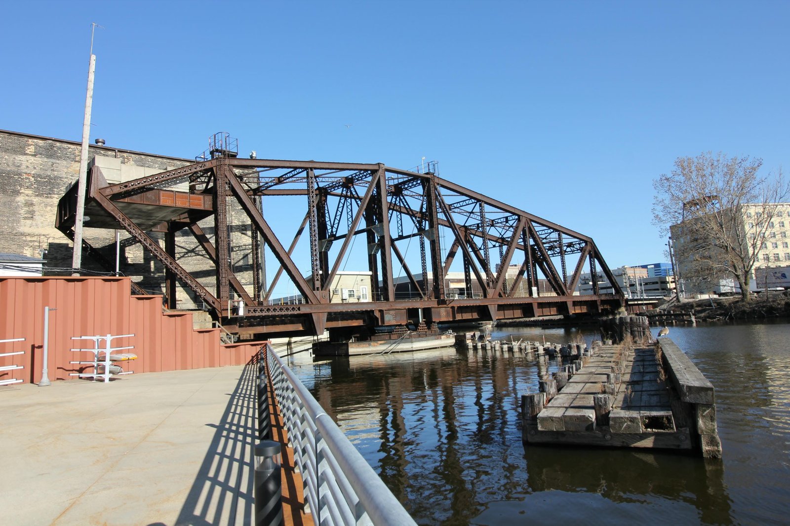
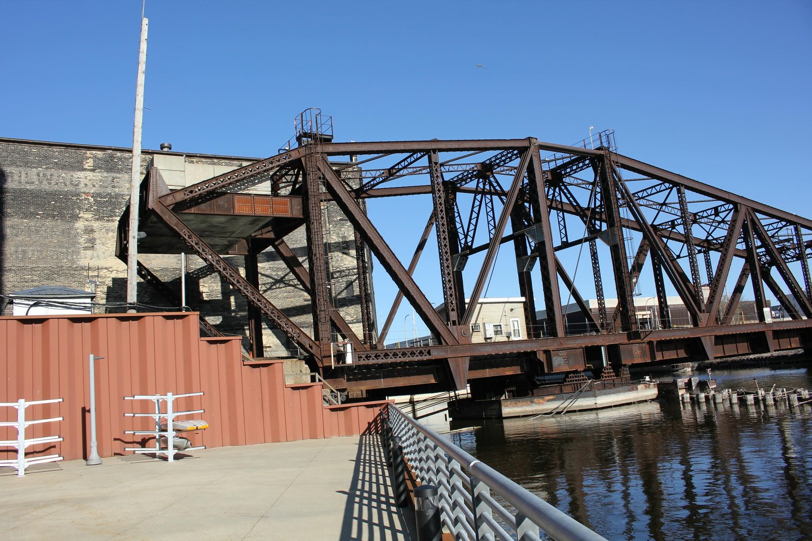
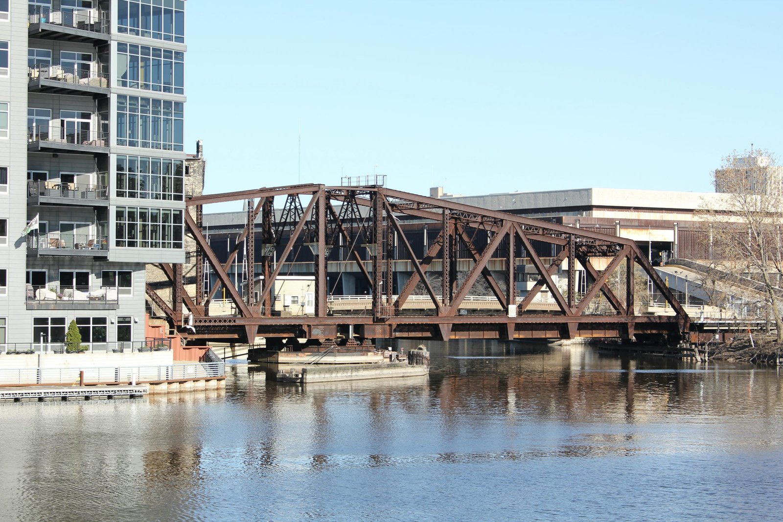
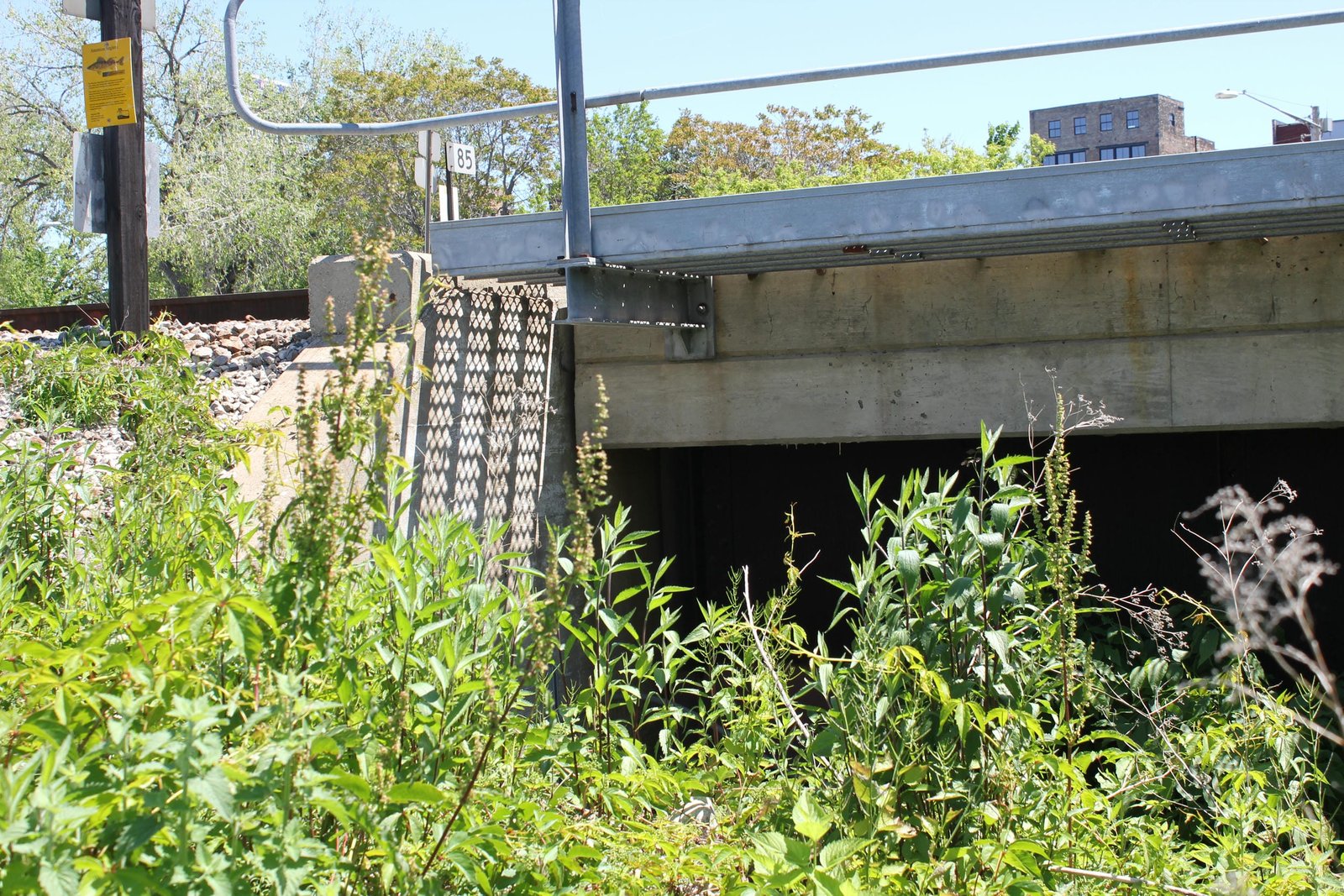
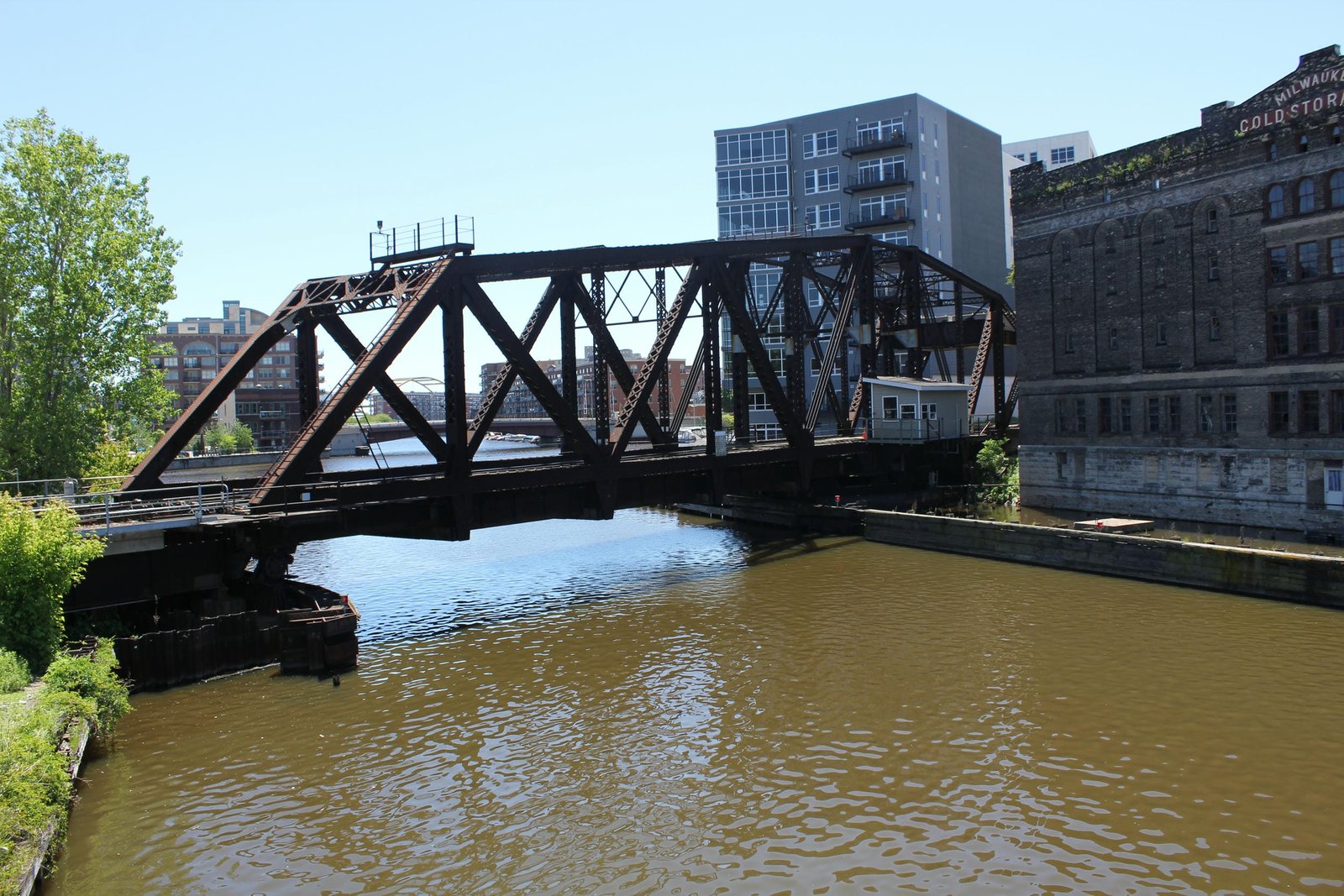
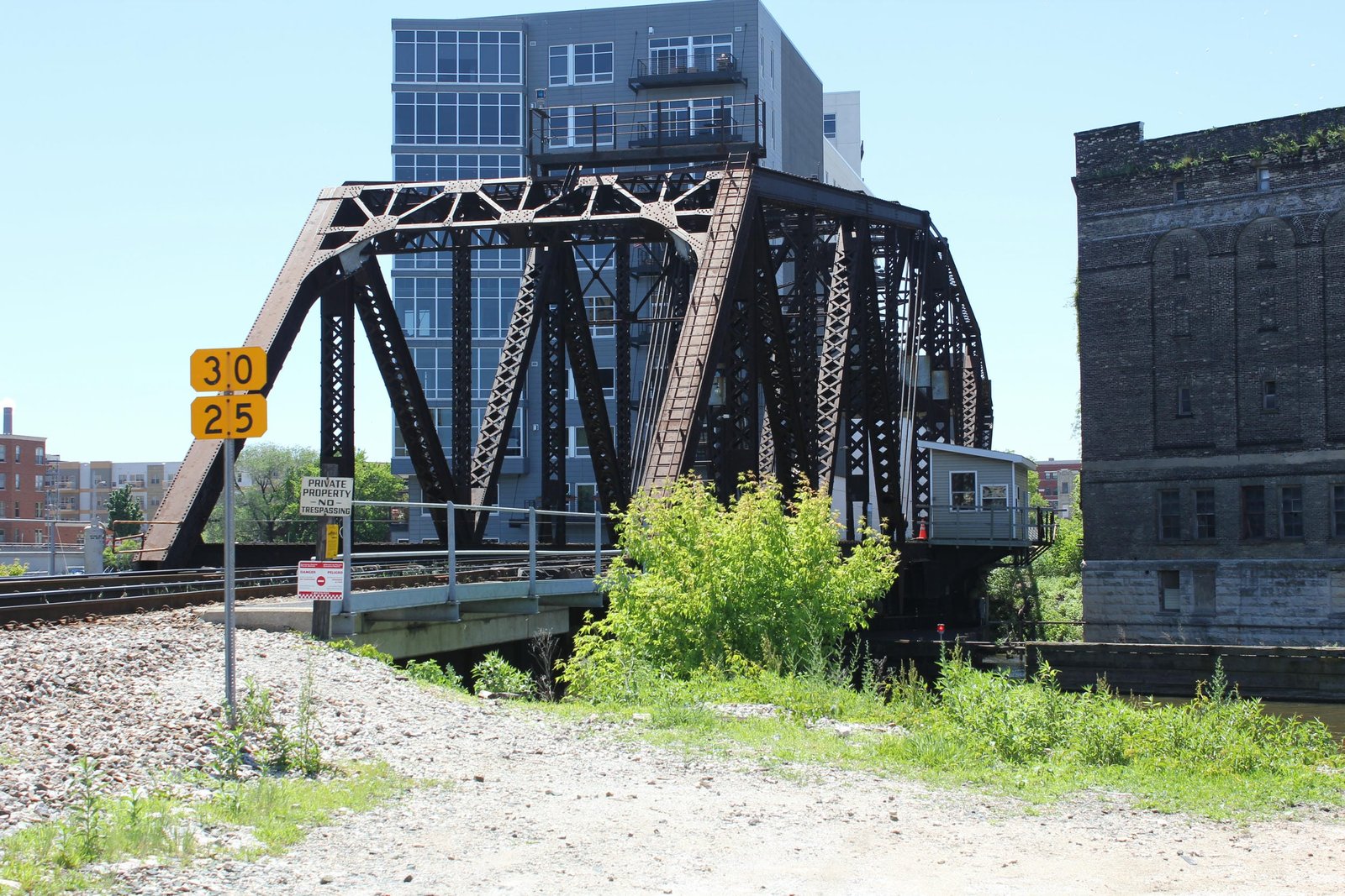
Located alongside Plankinton Avenue in downtown Milwaukee, this unique counterbalanced through truss swing bridge carries the former Chicago, Milwaukee, St. Paul & Pacific Railroad (Milwaukee Road) over the Menomonee River. The first bridge at this location was likely a single track wooden truss bridge, constructed when the line was first built. It is unknown if this bridge was upgraded during the 1870s. In 1886, the bridge was replaced by a 203-foot symmetrical rim-bearing swing span, fabricated by the Edge Moor Bridge Works. This span was lightly built, using a pin-connected Pratt design and an unusual crested shape. Members of the bridge were lightly constructed with built-up beams and eyebars, and the portal bracing of the bridge was a large decorative lattice design. By the turn of the 20th Century, the 1880s-era swing bridges in Milwaukee had become too light for traffic, and the Milwaukee Road began making plans to replace the structures. In addition, the City of Milwaukee sought to widen the navigation channel of the Menomonee River from 50 to 75 feet. To accommodate the wider channel, it was decided to use another 203-foot span, with the center pier shifted 42 feet south of the original pier. This design would require a counterbalanced span with a large concrete counterweight. Because this structure was one of the busiest bridges on the Milwaukee Road, it was paramount to keep a crossing in service while the new bridge was constructed.
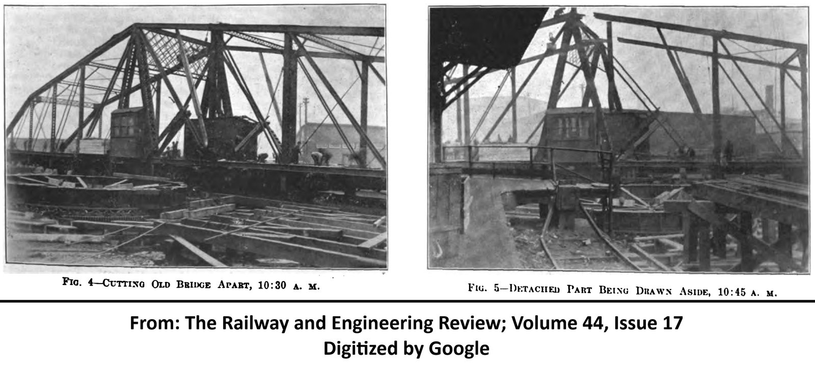
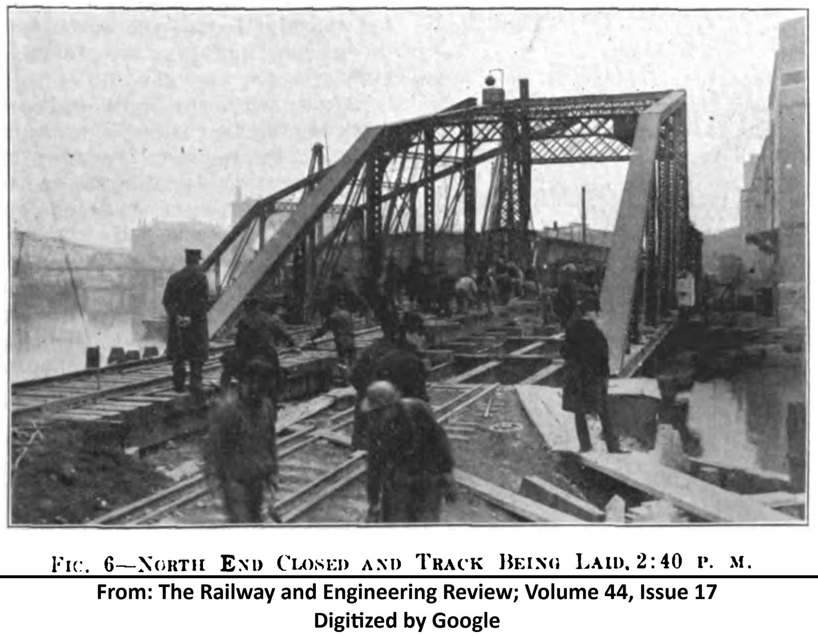
Other designs, including a bascule lift span were considered. However, the counterbalanced swing span was chosen due to its simplicity, lower initial cost and minimal impacts on adjacent properties. The chosen construction method was to open the old bridge, place the south arm on scows and cut it away from the bridge. The north arm would then be placed onto falsework, and a single track trestle would carry the tracks where the south arm once stood. This work was completed on April 5, 1904; with the bridge opening at 7 am and the first train passing over the temporary structure at 5 pm. Upon completion of the south (counterweight) arm of the new bridge, the north arm was constructed in a similar fashion. After both arms were completed, the remainder of the old pier and temporary falsework were removed. All work was done by Bridge & Building Department labor under the direction of Charles F. Loweth, who also oversaw the design and construction sequencing. James J. Harding, Assistant Engineer, also contributed to designing the new bridge; and American Bridge Company fabricated the new structure at their Lassig Plant in Chicago. While the original intention was to reuse the old abutments, it is unclear if this happened. The structure constructed uses a concrete south abutment and a deck plate girder approach on the north end. The most recent alterations to the bridge came in approximately 2000, when the original north approach was replaced by modern span of the same design, and the truss span saw a number of alterations.
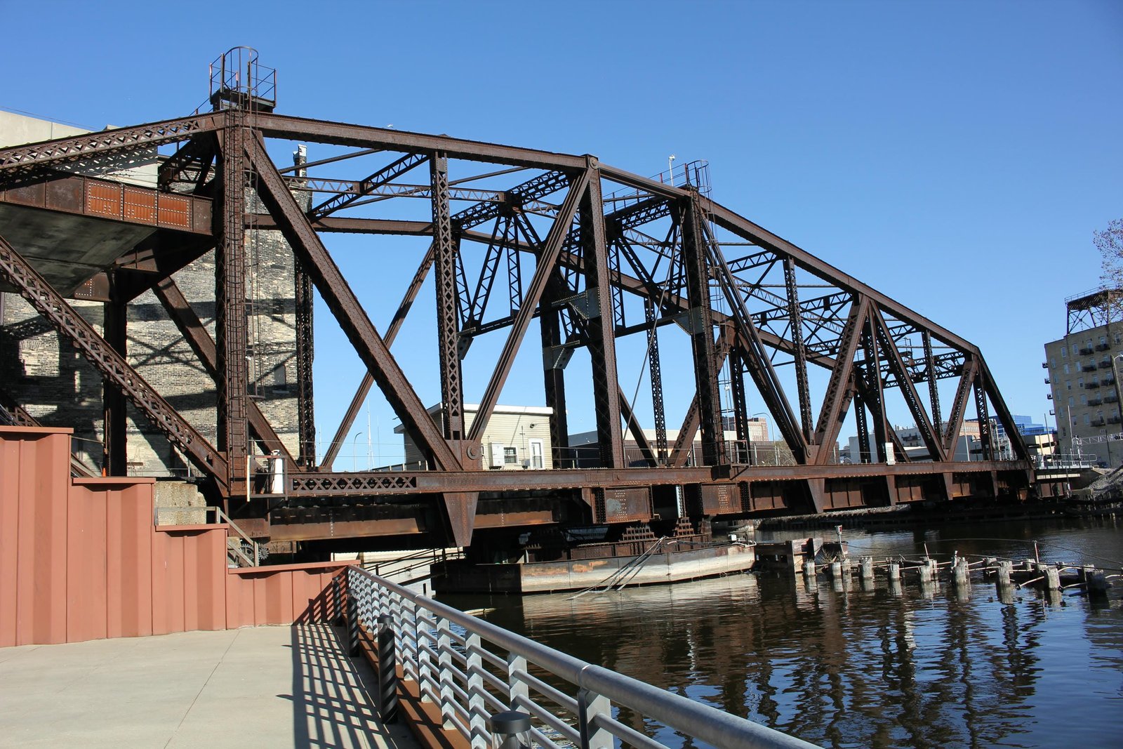
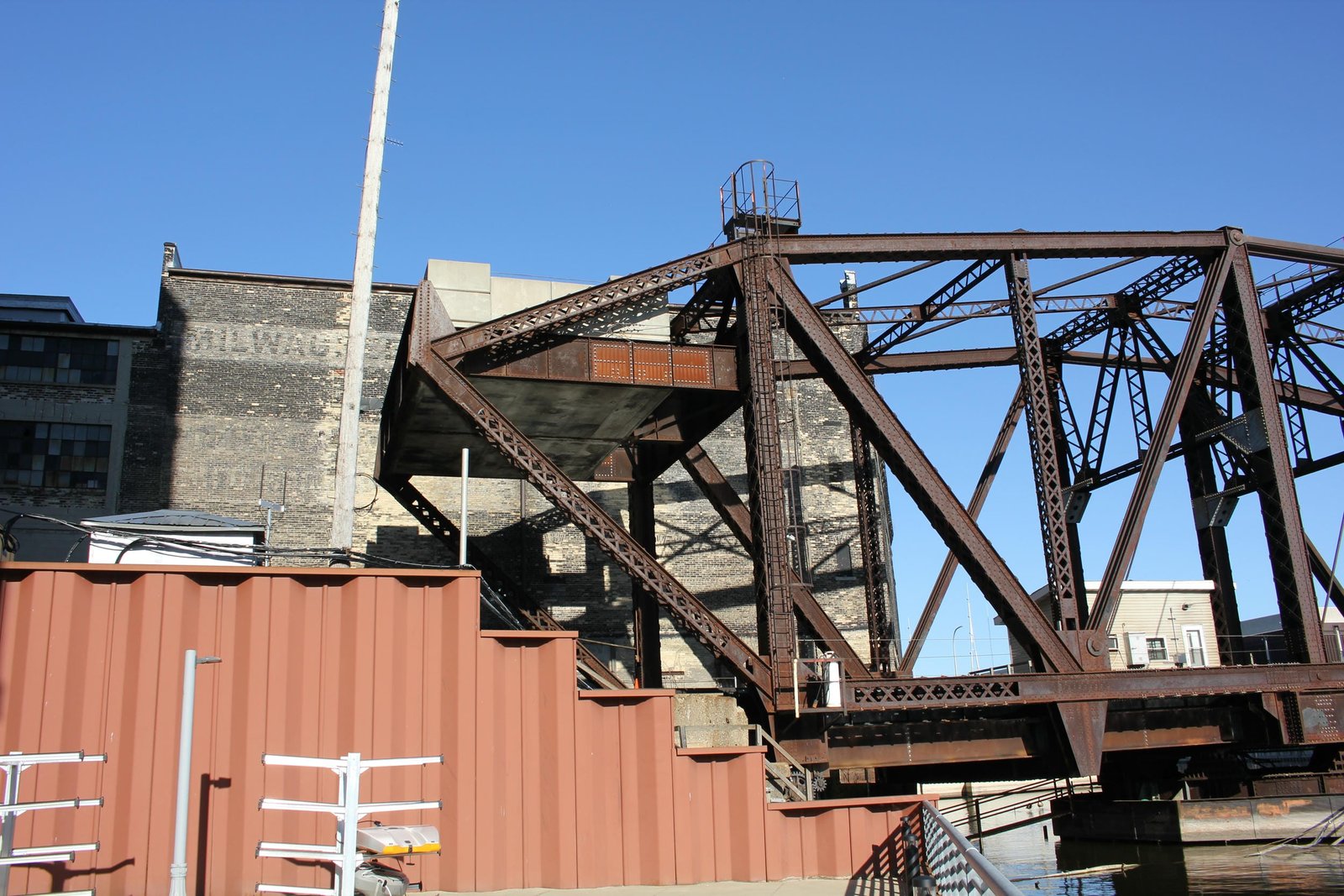
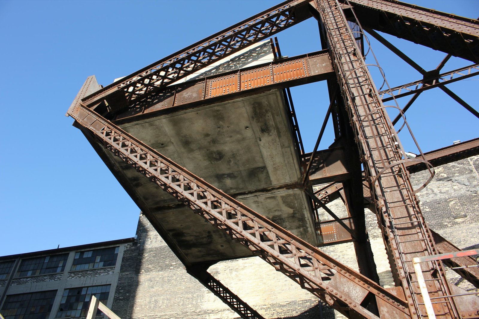
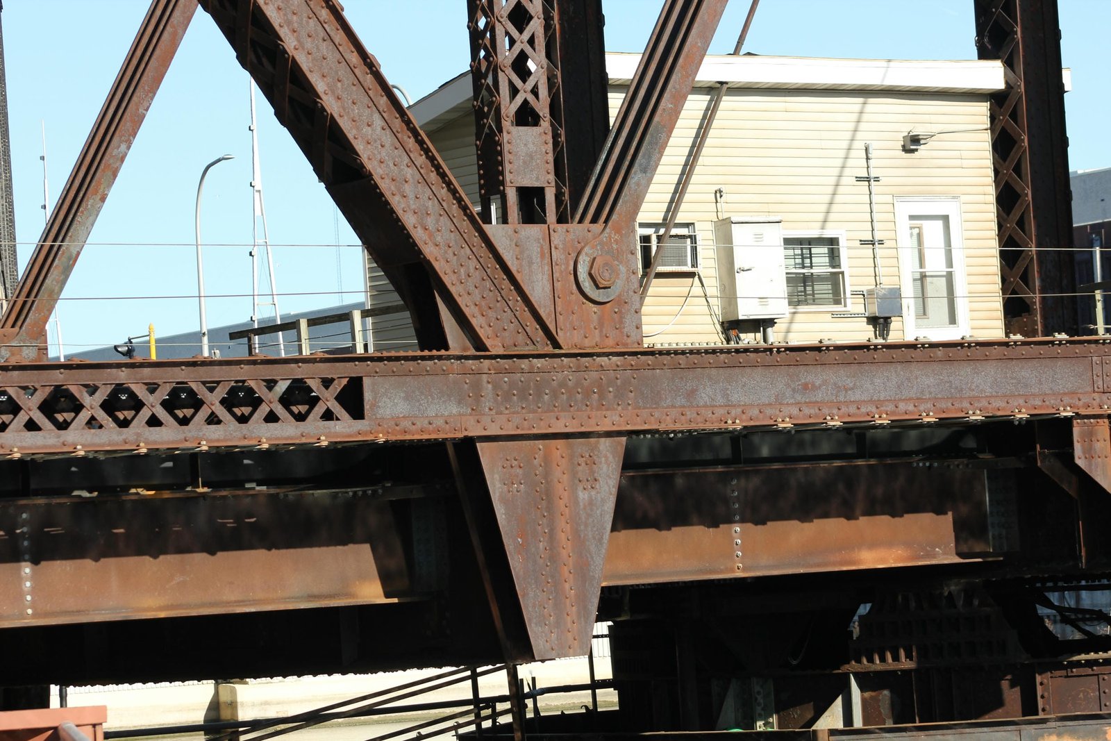
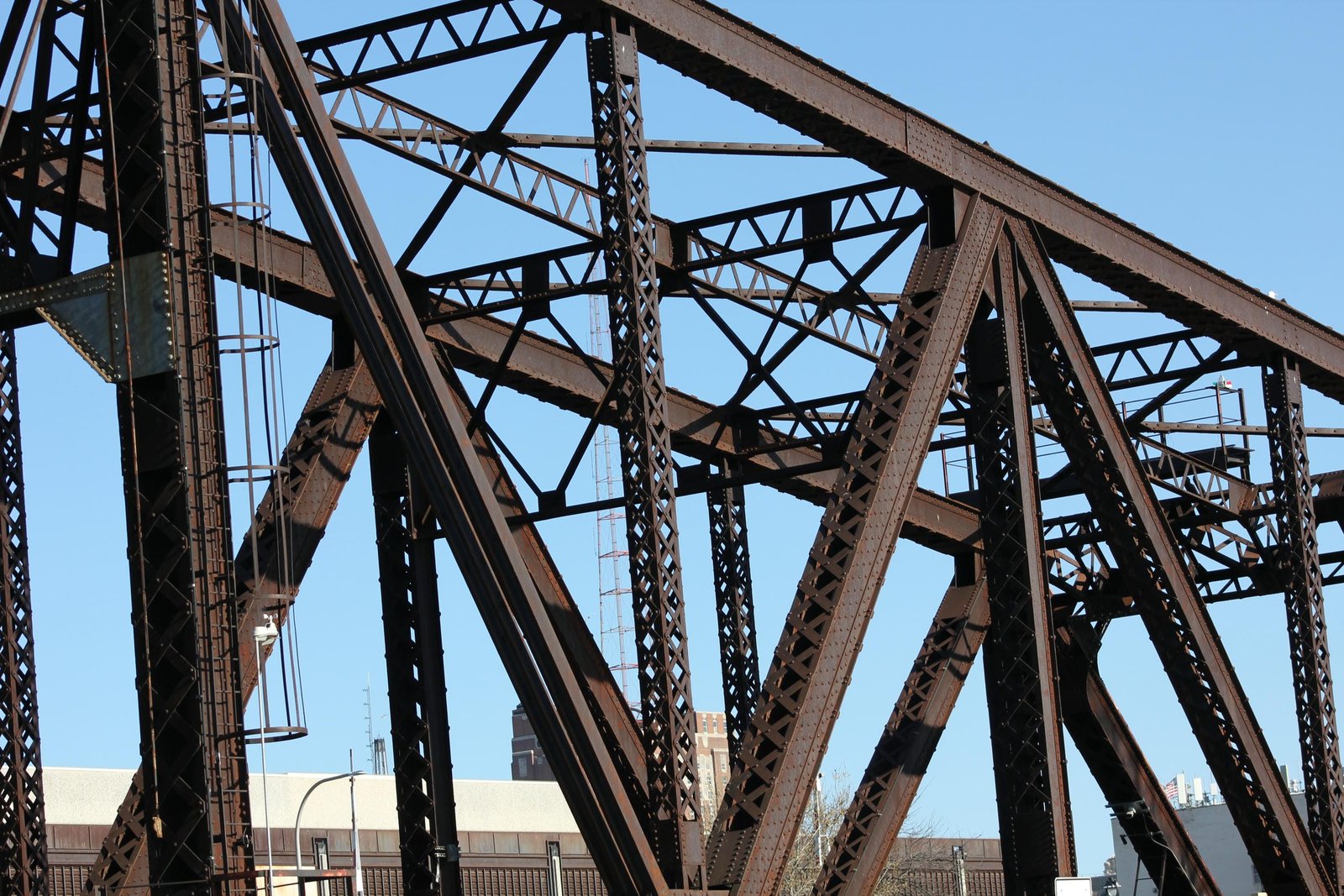
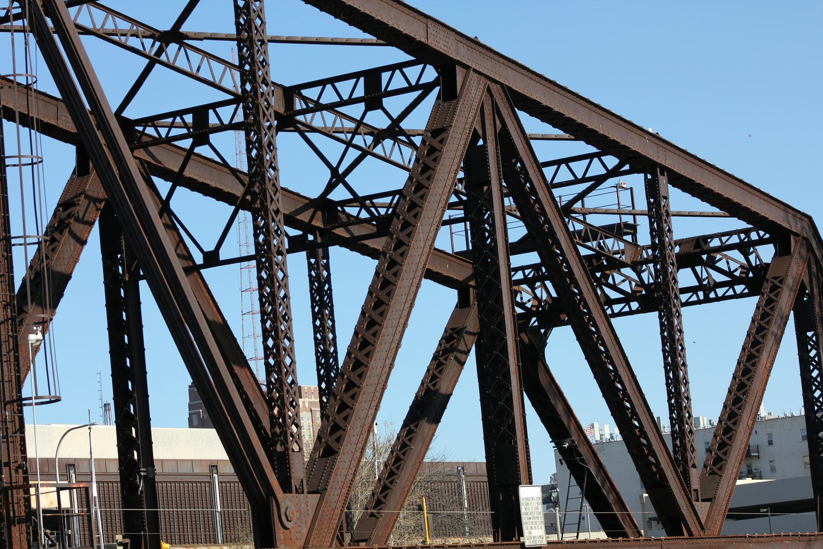
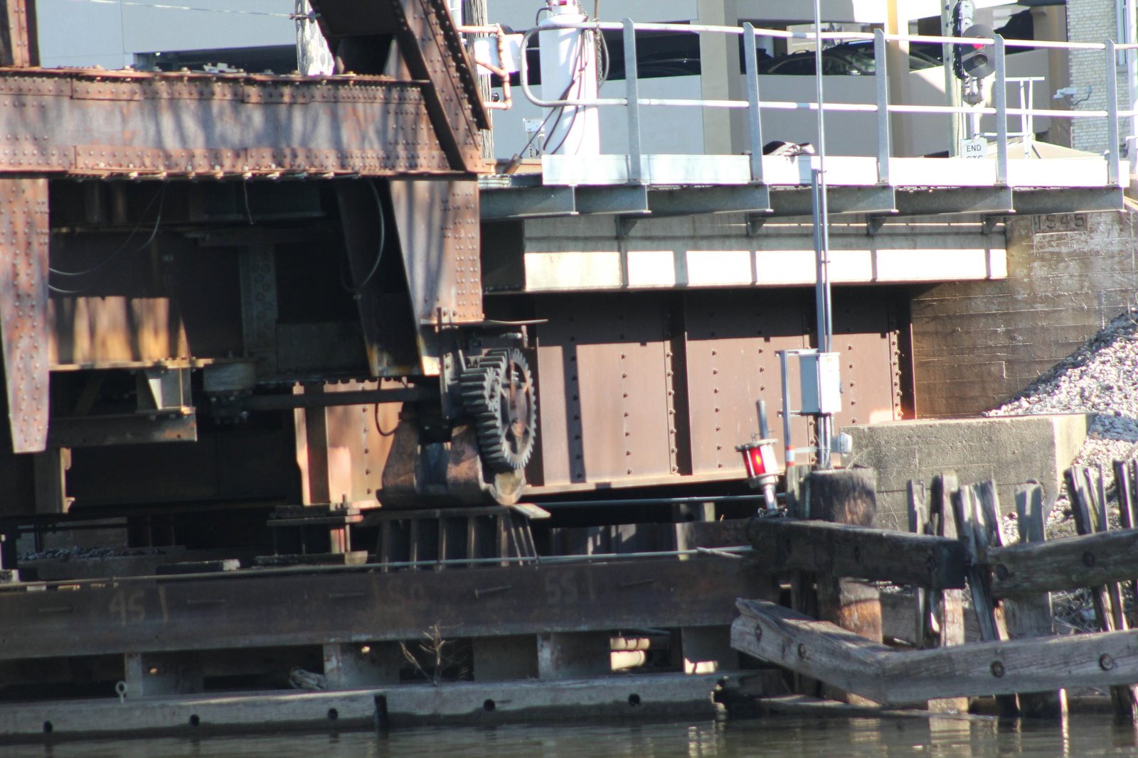
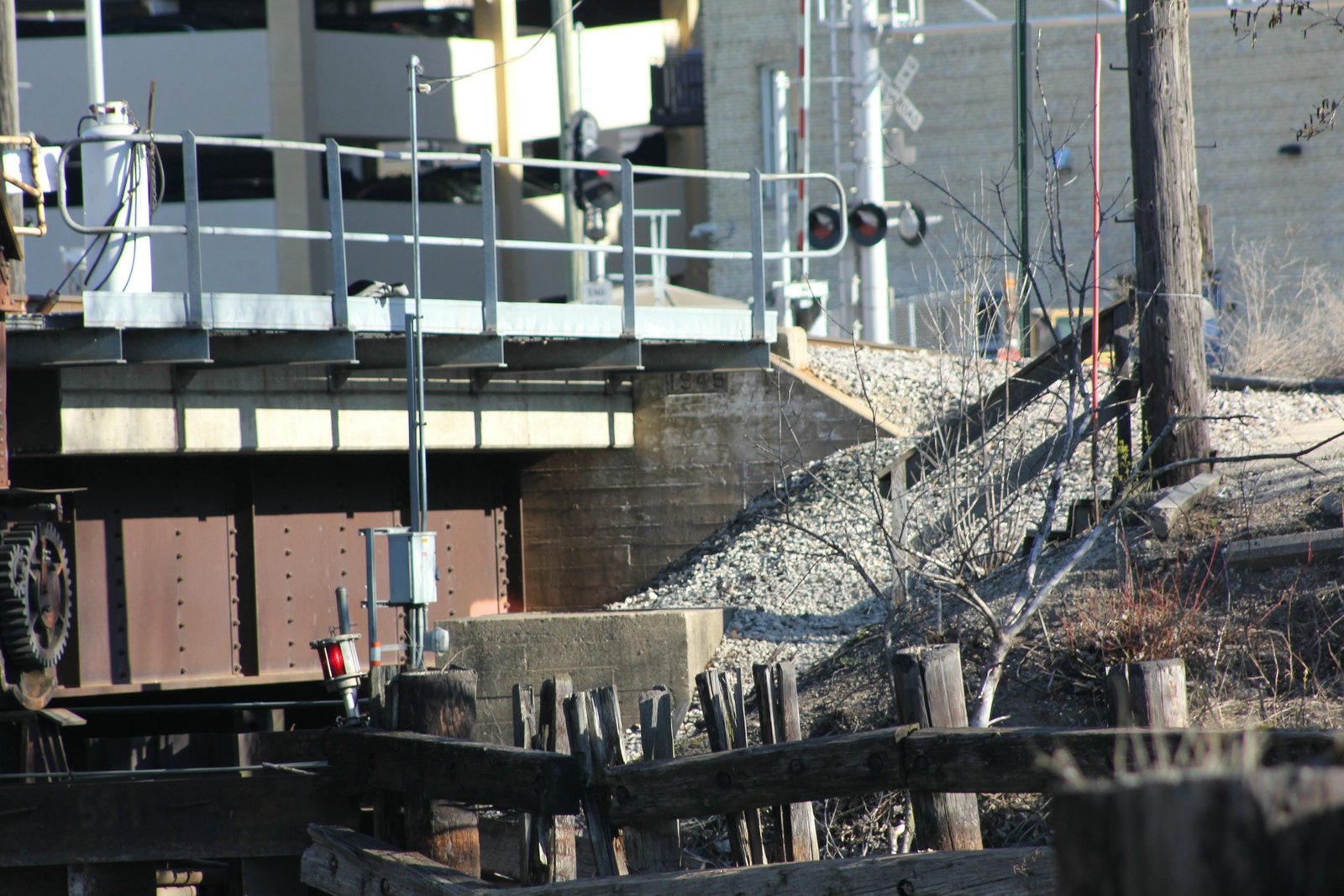
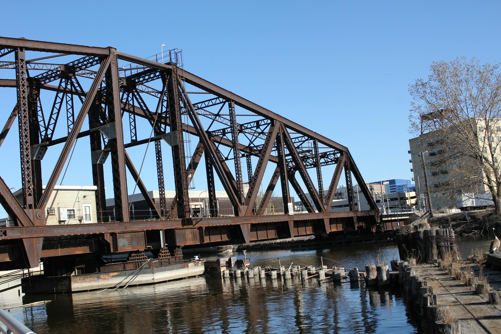
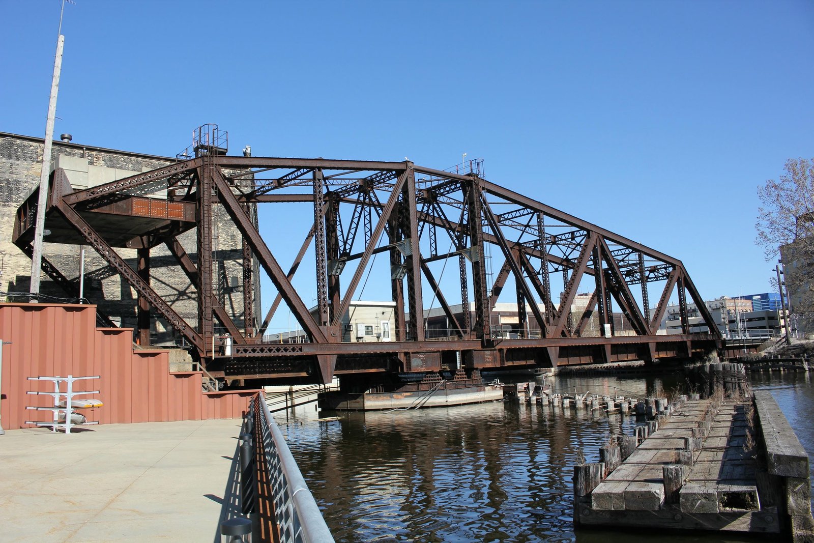
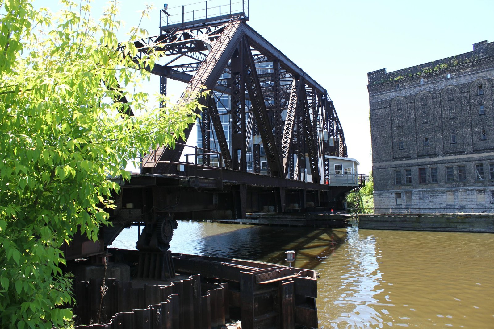
Currently, the bridge consists of a 203-foot, riveted counterbalanced Warren through truss swing span, approached by a 40-foot deck plate girder span on the north end. The entire bridge is set onto concrete substructures, which are founded on timber piles. The swing span is divided into four unique sections: a 133-foot, 5-panel north arm; a 21-foot, 1-panel center section, a 49-foot, 2-panel south arm and a 24-foot, 1-panel overhanging counterweight arm. The swing span uses a rim-bearing design, where the superstructure is set onto a steel drum, which rotates about a roller nest and is driven by a gear system. Unlike many similar rim-bearing spans, the superstructure is placed onto blocking, which rests on the drum. This may be a later addition, or may have been required to raise the height of the bridge. Further evidence of possibly raising the height of the bridge can be seen at the end bearings, where the original lift mechanisms are now placed on tall bearing blocks. Due to the unusual nature of this bridge, a number of unique design features are found throughout the truss span. Some of these features include a variety of types of built-up beams, unusual bracing and unique connections.
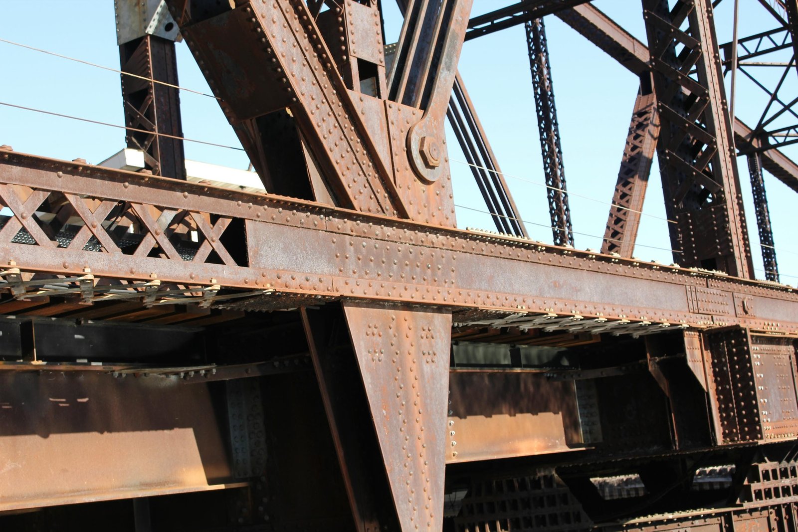
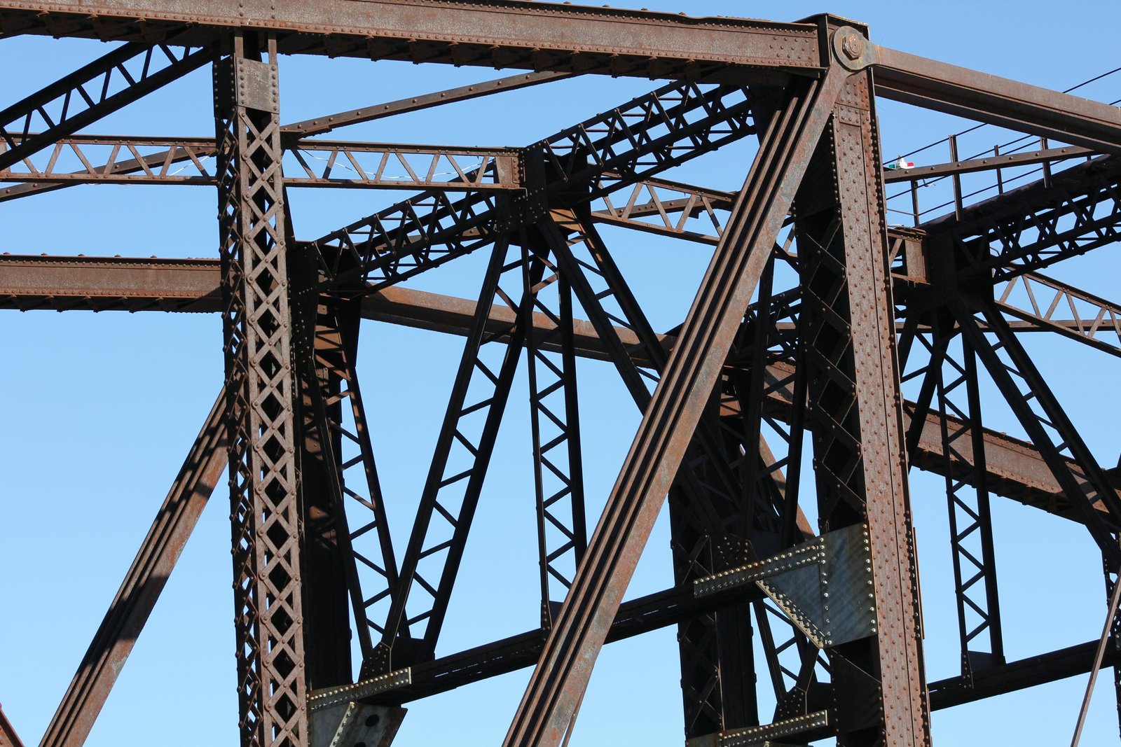
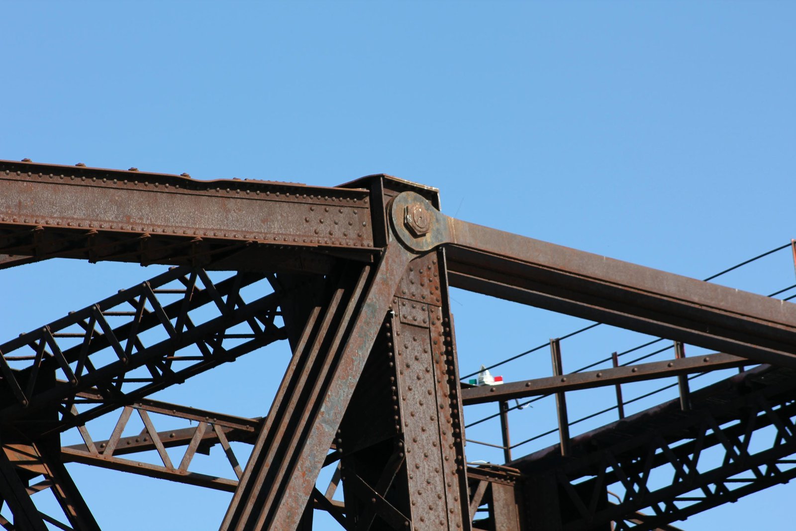
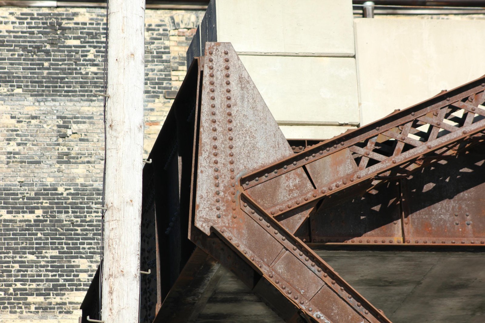
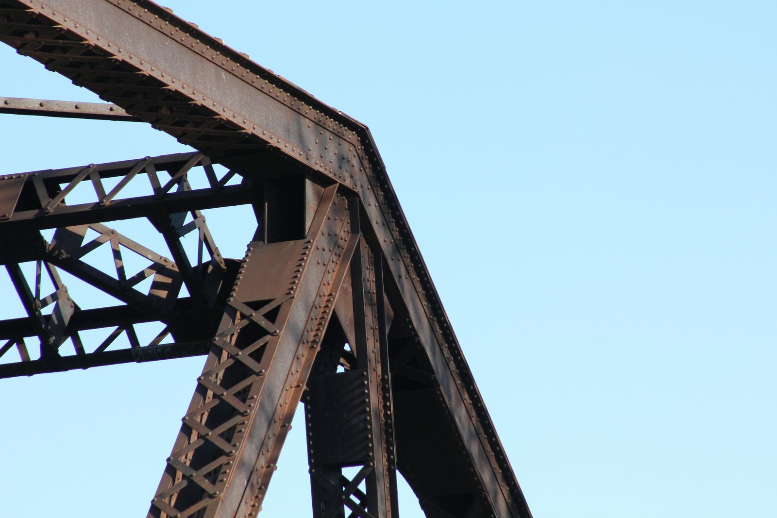
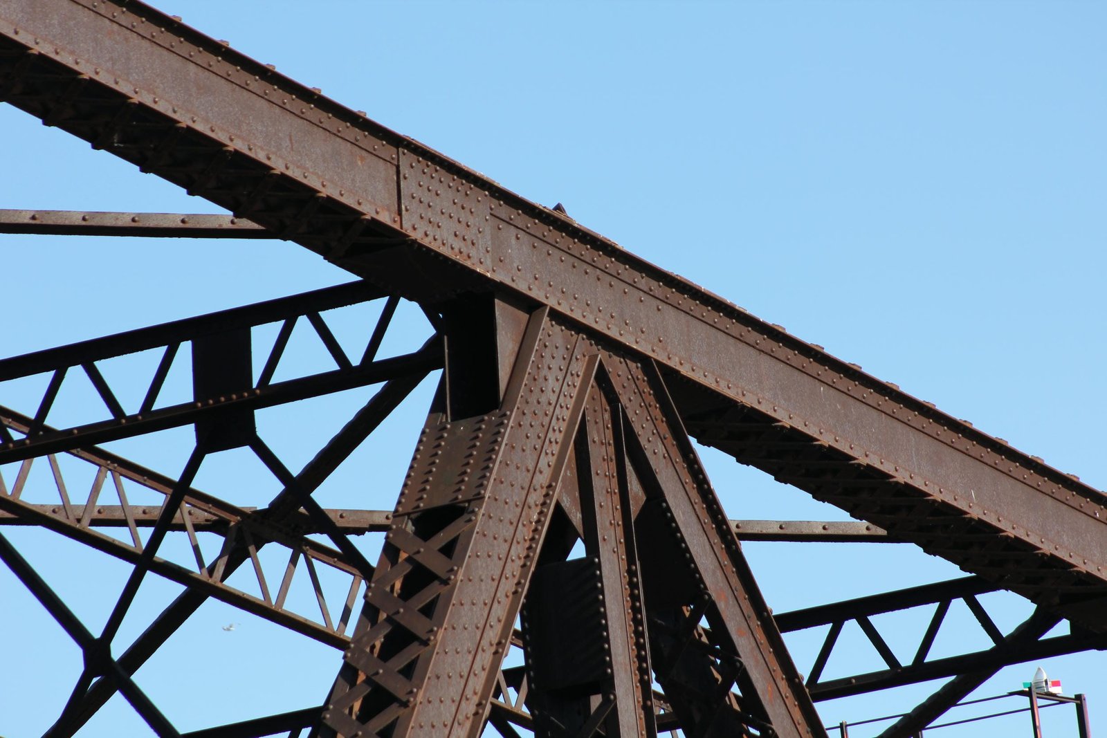
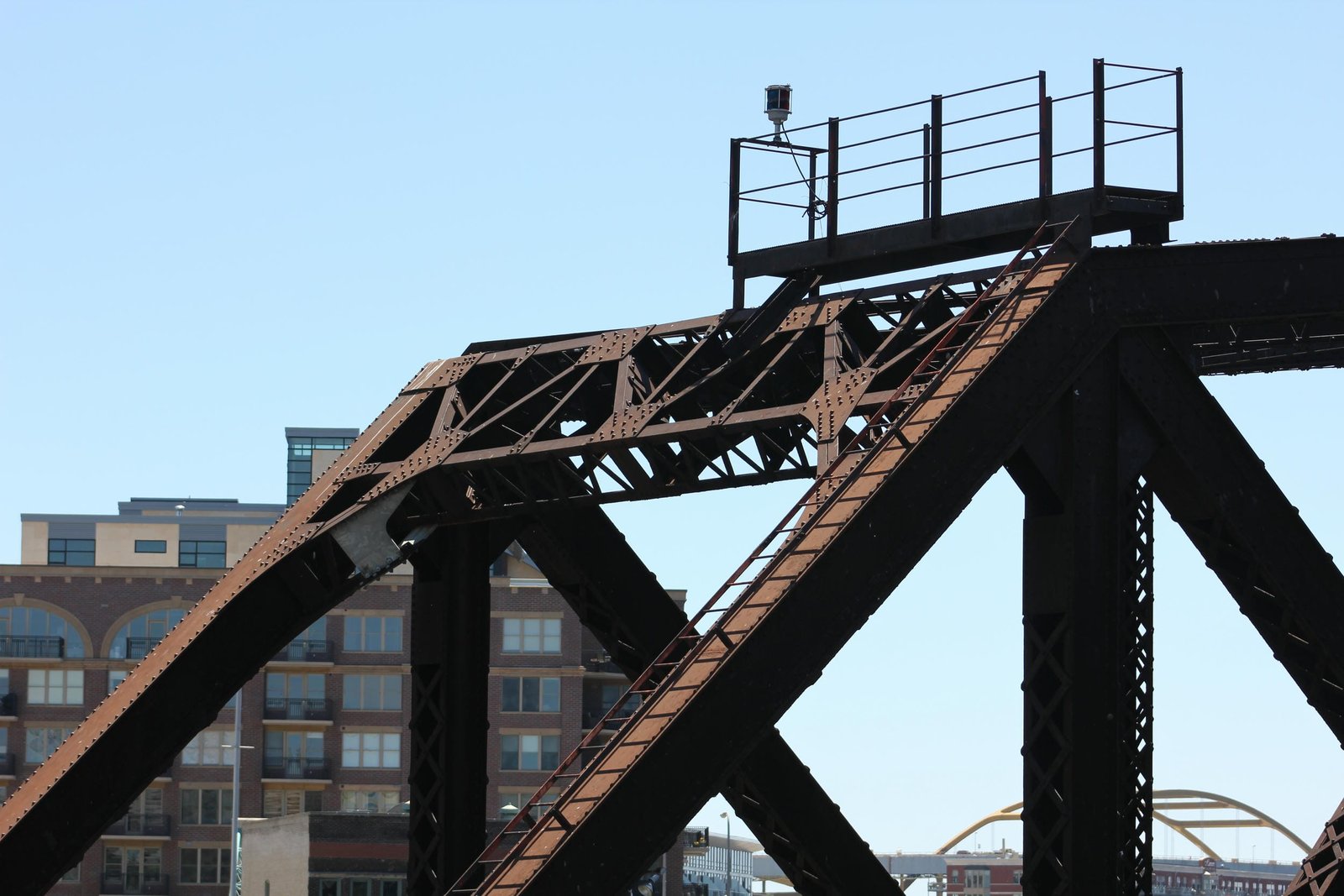
The top chord of both the north and south arms is constructed of built-up beams, connected by X-lacing on both sides. The endpost of the north arm is constructed of a built-up beam, connected by X-lacing on the interior and a solid plate on the exterior. Because of the geometry of the south arm, there is no inclined endpost, and instead the vertical endpost consists of a built-up beam with X-lacing on both sides. The bottom chord is mainly constructed of a similar built-up beam, with the exception of the southernmost panel on the south arm, which uses X-lacing on all four sides. Some vertical members are constructed of built-up beams with X-lacing on all four sides, while the remaining vertical members use built-up beams with X-lacing on two sides. With the exception of the diagonal members connecting the arms to the center section, all diagonal members are constructed of built-up beams with X-lacing on two sides. The center section is surrounded by a vertical member on all four corners, and only one thin rod connects the top of the north vertical member to the bottom of the south vertical member. Longitudinal eyebars connect the tops of the north and south vertical members on each side of the track. Each arm is connected to these vertical members by a series of four heavily constructed eyebars, which use pinned connections where they connect. These eyebars are connected to the bottom chord by use of a large gusset plate, which contains a riveted connection on the opposite side. The floor uses a standard design, with plate girder floorbeams at the panel points and plate girder stringers supporting the tracks. While the floorbeams appear original to the structure, the south arm stringers appear to have been replaced with modern I-beams around the turn of the 21st Century. The floorbeams are connected to the bottom chord by large trapezoidal plates. Various additional repairs have been made, including replacing plates at the center vertical members and additional rivet replacement with high-strength bolts.
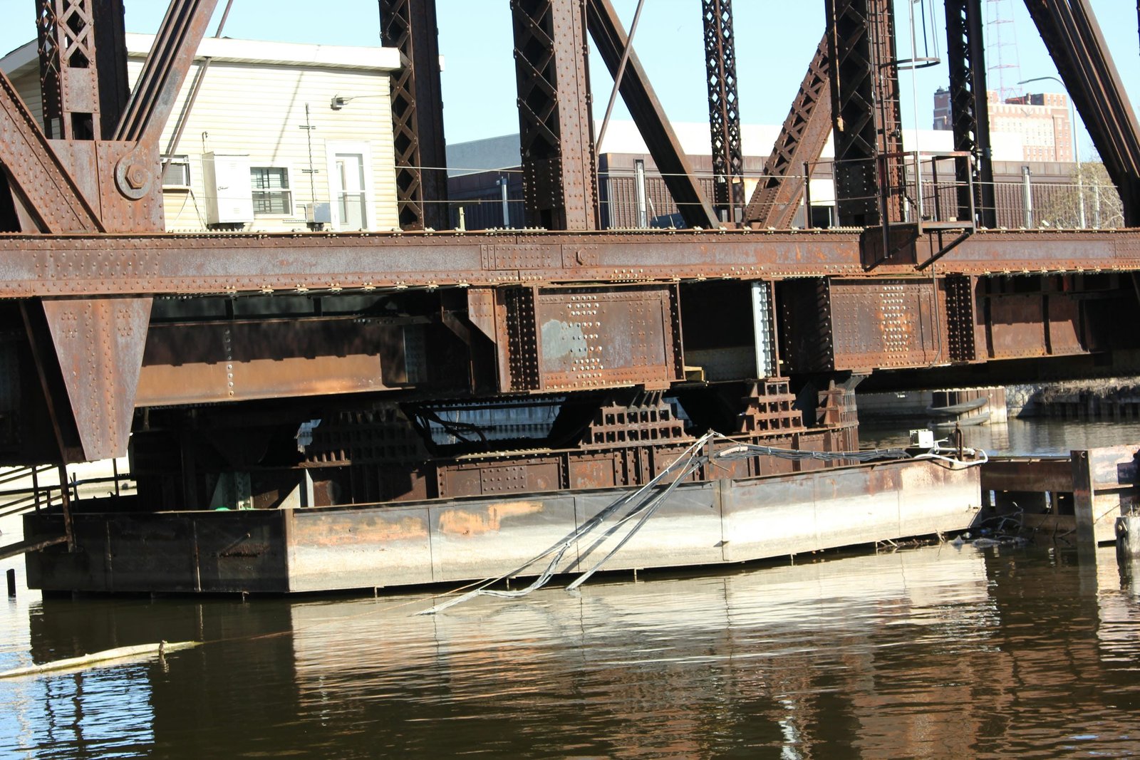
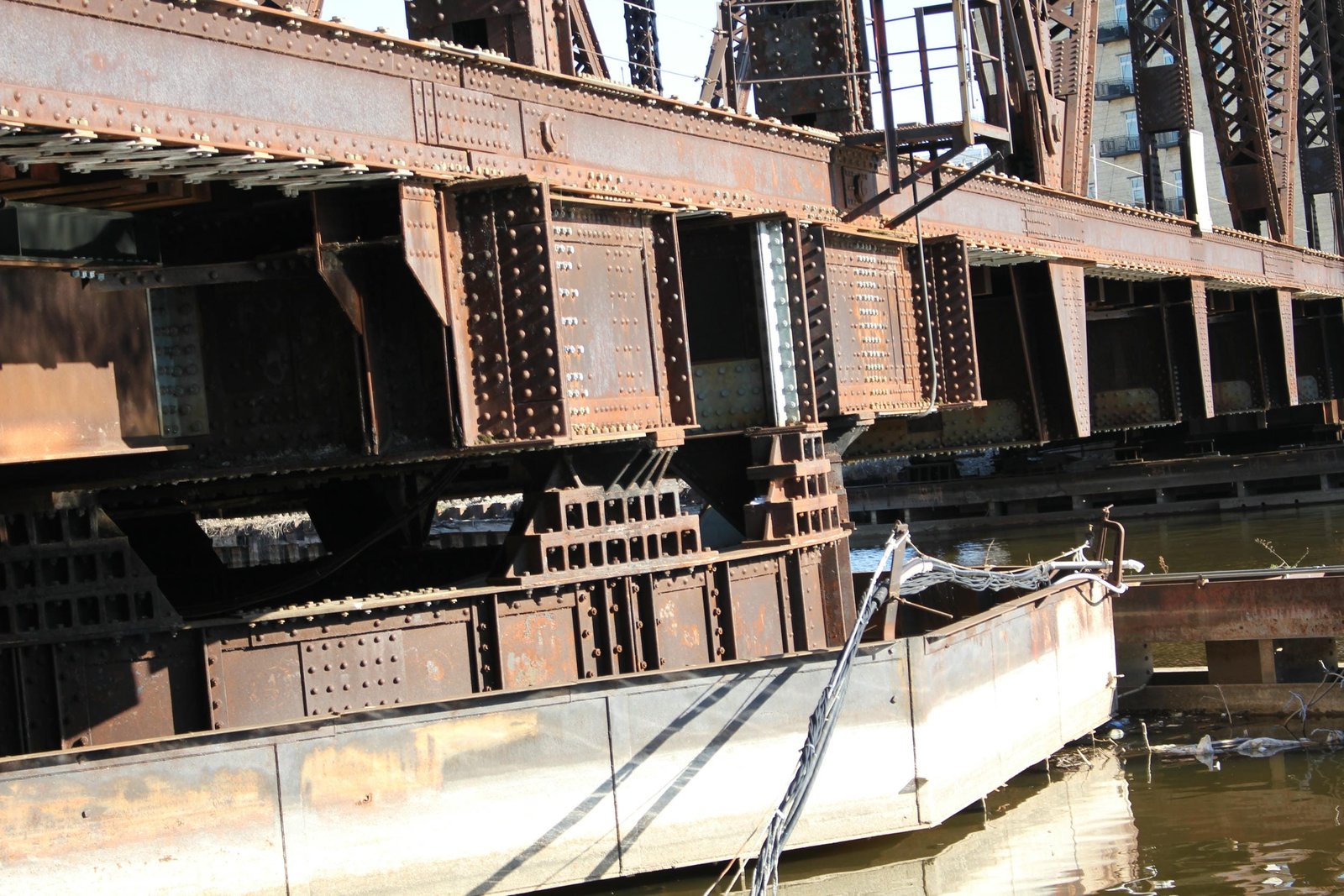
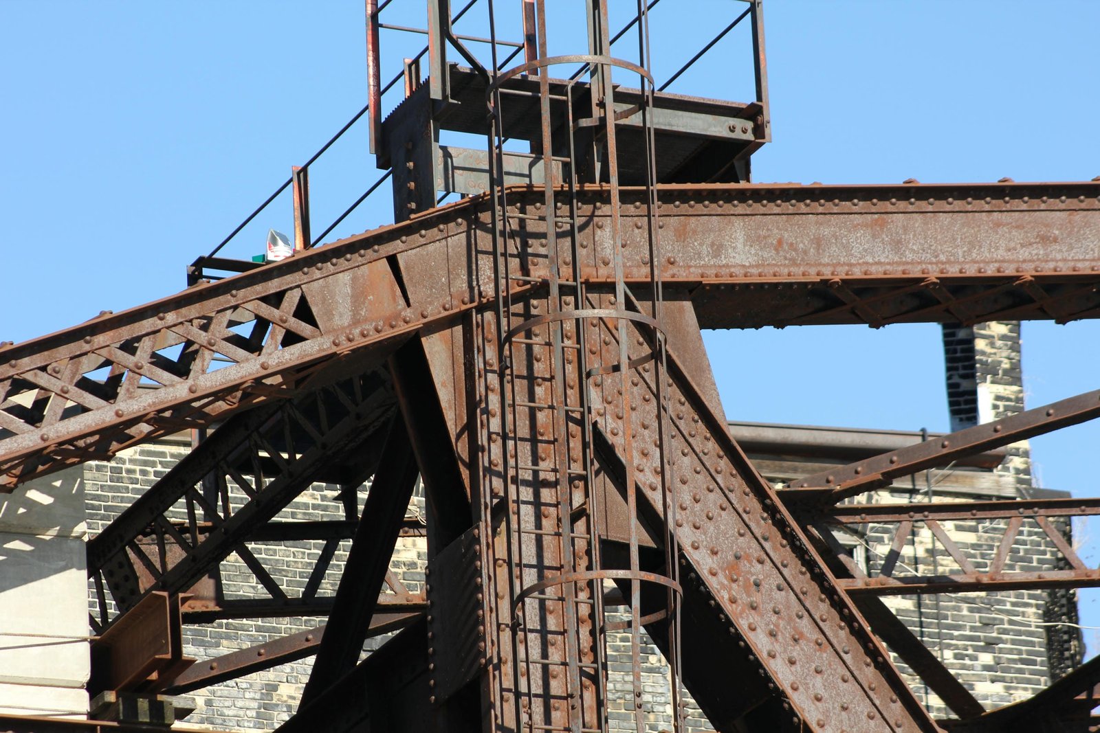
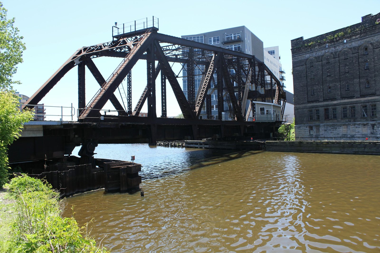
The counterweight system consists of three large plate girders, connected by transverse I-beams. The transverse I-beams are encased in concrete, and the system is balanced on the overhanging panel. This counterweight weights approximately 450,000 pounds; and its placement beyond the end of the abutment reduced the amount of concrete needed. The counterweight is supported by a triangular shaped arm, with the counterweight set at approximately 3/4 height. Additional concrete panels have been added to the counterweight, possibly to offset the additional weight from various repairs to the bridge. The members of this arm are constructed using built-up beams with X-lacing on all four sides. The portal bracing of the north arm is constructed using a modified M-frame design, built out of V-laced beams. Three different designs of sway bracing are used. Sway bracing at the vertical members surrounding the center section consist of a W-shape, constructed of built-up V-laced beams. The top strut is composed of a square beam with V-lacing on all four sides, while the bottom strut is constructed of a solid beam. In the middle of the north leaf, the sway bracing uses a lattice design, with a V-laced top strut and thin bar for the bottom strut. The remainder of the sway bracing is simply composed of a V-laced strut. In addition to the sway bracing, a longitudinal V-laced beam is located between the tops of the trusses and runs the entire length of the span. The upper and lower lateral bracing are both constructed out of solid bars. The substructures largely use a standard design, and the center pier is constructed in an octagonal shape, which has been reinforced with sheet metal.
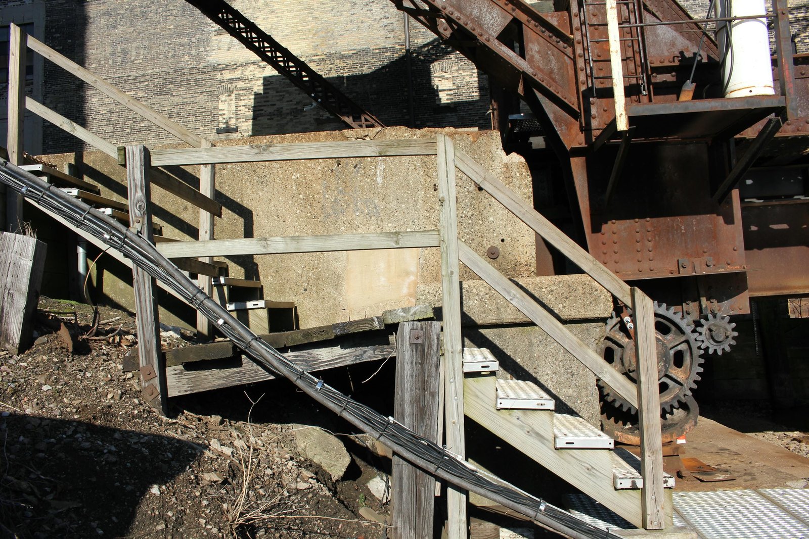
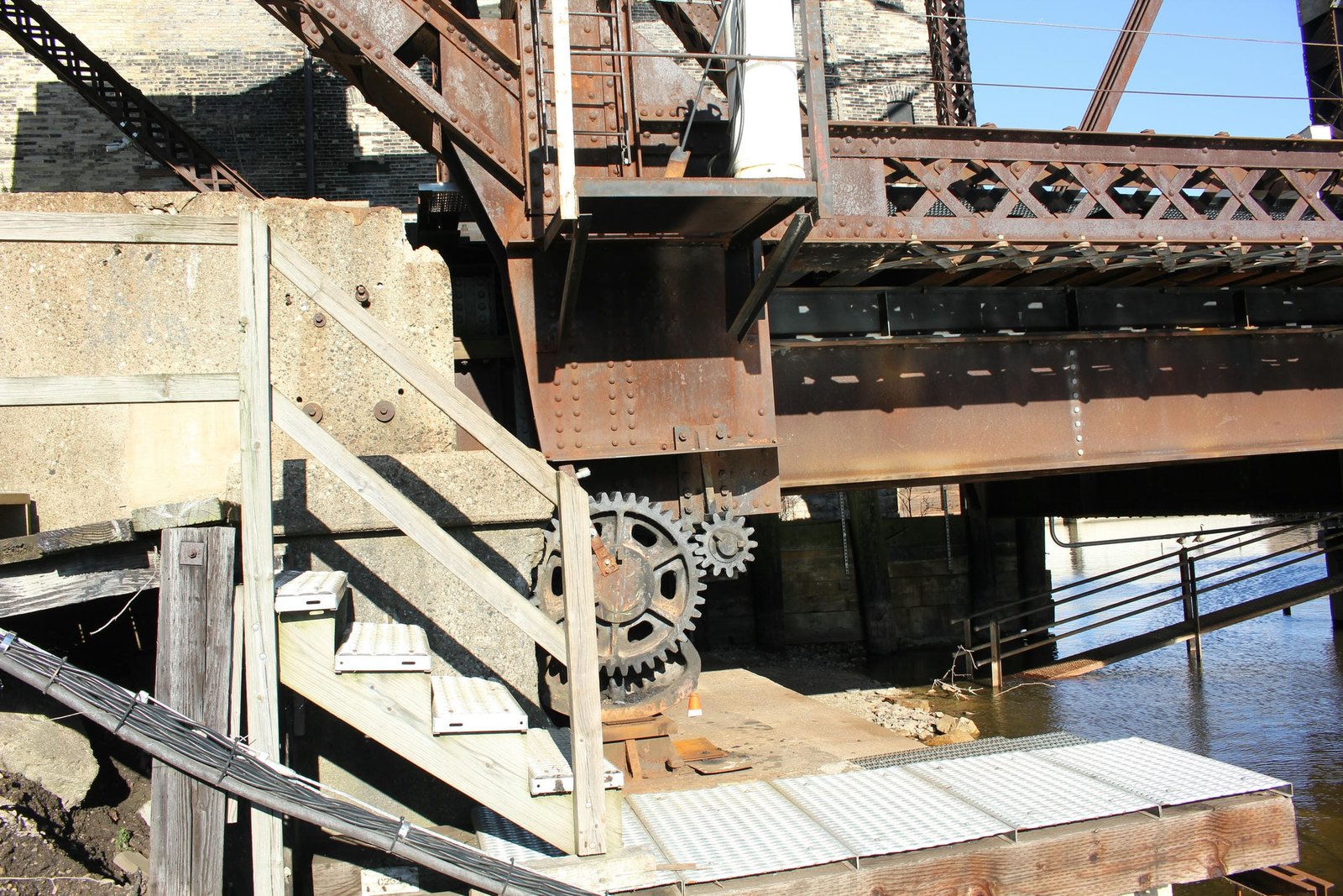
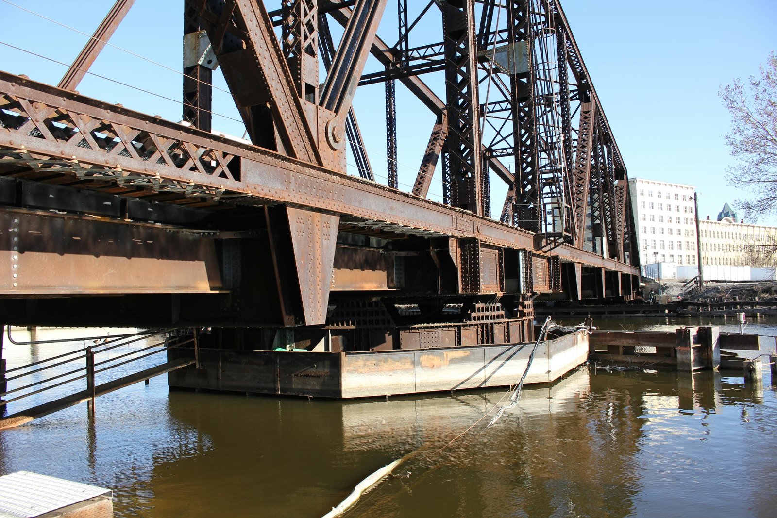
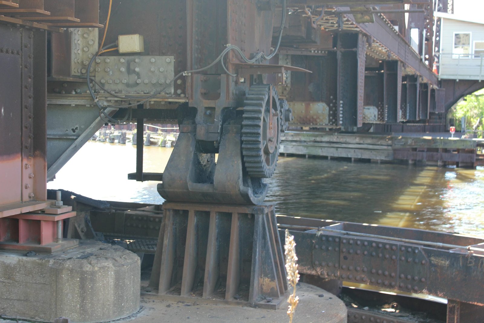
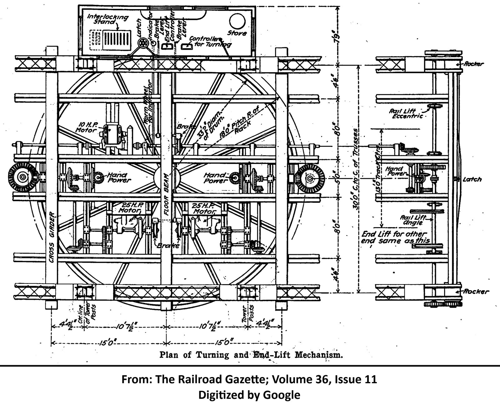
This bridge also varies from traditional swing bridges in the lifting, locking and rotating mechanisms. When operating, the rail lifts at the end of the bridge are first operated. These mechanisms lift the rail, and allow the bridge to swing freely. Next, the locking mechanism is lifted, and the span is rotated slightly, before the operator engages the motor of the rotating mechanism. The operator then stops the rotation by cutting power to the motor or by applying a brake. Many traditional swing spans use wedges driven at the end to lift the span after the locking mechanism was disengaged. The Milwaukee Road designed a different mechanism for this function. At the end of the span, a cam shaped end lift shoe rotates about an axis perpendicular to the railroad, causing the span to raise or lower. In closed position, this shoe acts as a rocker bearing, absorbing small expansions and contractions. A shaft running longitudinally under the bridge carries power from the motor to the end shoes. The pivot mechanism on this bridge utilizes a rim-bearing design, where a drum constructed of plate girders rides on a circular track of rollers, which carries the bridges entire weight. A pin at the center of the track maintains the proper alignment of the bridge. The drum constructed for this bridge is a two-part structure. Two separate square drums are located offset of the center of the center panel, and one large transverse girder is located in the exact center. This helps evenly spread the weight of the bridge, and provides room for the machinery. The top portion of the drum is placed onto blocks, which are located on a round drum constructed of plate girders. This drum is placed directly onto the roller nest, and is supported from the center pin by use of radial girders. Machinery for operating the bridge is located within the center pier, and is controlled from a machinery house located on the west side of the bridge. Because the river remains navigable, the swing span still operates when needed.
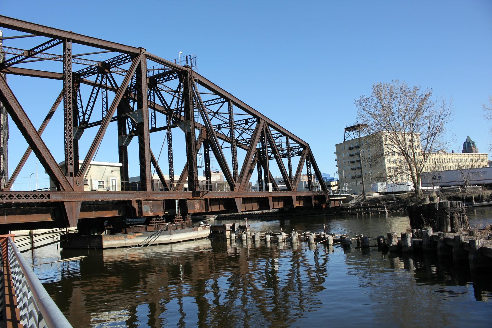
Counterbalanced, or "bobtail" spans, were infrequently used by railroads. These spans provided most of the drawbacks of a symmetrical swing span, with additional weaknesses in the counterbalanced design. Counterbalanced spans required precise calculations, additional costs and often required difficult engineering. This type of swing span utilizes a large counterweight on one arm (the counterweight arm), which offsets the longer length of the main arm of the span. Due to the different lengths, a counterbalanced swing span cannot rotate a full 360 degrees, and instead must come to a stop and rotate the opposite direction during opening and closing operations. While the additional time needed to stop and restart amounts to mere minutes, the additional time was often considered inadequate for railroads. The Milwaukee Road designed and implemented a number of counterbalanced swing spans throughout the system, constructing the most known spans of any railroad in the United States. Of these spans, three were constructed in Milwaukee, including additional spans across Burnham Canal and the Kinnickinnic River. Because the Milwaukee Road designed and constructed so many counterbalanced swing spans, the design was altered as needed, using both plate girder and truss designs. Many Milwaukee Road designed counterbalanced spans remain intact today.
In the early 20th Century, many railroads were transitioning from using pin-connected Pratt truss spans to riveted Warren truss spans. Riveted Warren spans provide a greater rigidity and strength, while maintaining a simple and economical design. Earlier counterbalanced swing spans constructed by the Milwaukee Road used either plate girder designs, such as Bridge #Z-6 or a Pratt truss design, such as Bridge #Z-2. It appears that this may be the first counterbalanced swing span constructed by the Milwaukee Road to use a riveted Warren design. The bridge across Burnham Canal, constructed in 1907, was designed based on the plans for this bridge. Since the initial construction, the bridge has seen a number of alterations, which are detailed above. Despite these alterations, the bridge retains excellent historic integrity, and is one of only a handful of counterbalanced swing spans ever constructed in the United States. Unfortunately, CPKC, the current owner of the three Milwaukee counterbalanced spans plans to replace the Burnham Canal bridge, possibly as soon as 2026. It is also possible that this bridge and the Kinnickinnic River Bridge may also be replaced in later projects. Overall, the bridge appears to be in fair condition, with recent repairs hopefully extending the life of the bridge. The author has ranked this bridge as being highly significant, due to the unique and innovative design.
Citations
| Builder and build date | The Railroad Gazette; Volume 36, Issue 11 |
| Railroad History Citation | ICC Valuation Information, Compiled by Richard S. Steele |