


Click the photo to view the full-size version
| Name | Kate Shelley High Bridge Chicago & North Western Railway Bridge #615 |
| Built By | Chicago & North Western Railway |
| Currently Owned By | Union Pacific Railroad |
| Superstructure Contractor | American Bridge Company of New York (Various Shops) |
| Substructure Contractor | Widell Company of Mankato, Minnesota (Abutments and Pedestals) Engineering Contract Company of New York (Steel Cylinders) |
| Engineers | George S. Morison (Consulting Engineer) William H. Finley (Design Engineer) W.C. Armstrong (Resident Engineer) |
| Length | 2,685 Feet Total, 300 Foot Main Span |
| Width | 2 Tracks |
| Height Above Ground | 185 Feet |
| Superstructure Design | Baltimore Deck Truss and Deck Plate Girder |
| Substructure Design | Steel Tower, Stone Masonry and Steel Caisson |
| Date Built | 1899-1901; Rehabilitated 2001 |
| Traffic Count | 0 Trains/Day (Bridge is Closed To Traffic) |
| Current Status | Bypassed and Closed To Traffic |
| Chicago & North Western Railway Bridge Number | 615 |
| Union Pacific Railroad Bridge Number | 207.42 |
| Significance | National Significance |
| Documentation Date | 7/22/2012; 3/26/2013; 8/12/2013; 10/17/2017; 1/20/2018 |
In 1867, the Cedar Rapids & Missouri River Railroad (CR&MR) continued constructing a mainline westward from Boone, Iowa. In the late 1850s and early 1860s, the CR&MR had participated in constructing a line from Clinton, Iowa to Boone. The CR&MR was leased by the Chicago & North Western Railway (C&NW), which was seeking a route connecting Chicago to the Missouri River. In 1867, an impressive 150 miles were constructed between Boone, Iowa and Council Bluffs, Iowa, completing a connection between Chicago and the Missouri River. The line also allowed for a short spur from Missouri Valley, Iowa to the Missouri River opposite of Blair, Nebraska. This spur would eventually be extended across the Missouri River and into Nebraska. Between 1869 and 1872, Union Pacific Railroad (UP) constructed a bridge across the Missouri River between Council Bluffs and Omaha, Nebraska; and the C&NW obtained trackage rights over the bridge to reach Omaha. During the second half of the 19th Century, the C&NW had constructed and acquired a large amount of trackage throughout the Midwest. In 1884, the CR&MR was formally purchased by the C&NW; and this line quickly became a core asset of the C&NW system.
By the late 19th Century, traffic over this line had increased to the point significant upgrades were required. In 1893, a 5-mile section of railroad was relocated west of Jefferson, Iowa to improve grades and eliminate curves. One of the most significant barriers to efficient operation over this line was the Des Moines River Valley between Boone and Ogden, Iowa. The original route crossed the Des Moines River at Moingona, which was approached by winding and steep approaches on each bank. In 1899, C&NW subsidiary Boone County Railway (BCR) began construction on a more direct route between Boone and Ogden, Iowa; including a massive viaduct across the Des Moines River. The BCR was consolidated into the C&NW in 1900, and the new cutoff was completed in May 1901. The new alignment shortened the route by 3 miles, cut grades in half and only required two small curves. The original mainline through Moingona was maintained as an emergency backup and to serve industries in the area. Between 1901 and 1902, a second track was also constructed between Ogden and Council Bluffs, including a 5-mile realignment near Arcadia, Iowa. The double tracking of this line provided the C&NW with a well constructed double track mainline between Chicago and Council Bluffs.
By the 20th Century, the C&NW was operating an extensive railroad network, which radiated north and west from Chicago. The original mainline into Moingona was abandoned in 1930. This line served as the backbone of the C&NW, connecting transcontinental freight and passengers at Omaha to Chicago. Known as the Overland Route, this line became one of the most significant railroad routes in the United States. This route saw continuous upgrades during the 20th Century, including significant bridge, rail, tie and signal upgrades. In 1995, the C&NW was purchased by UP, which provided UP with a mainline into the railroad hub of Chicago. Into the 21st Century, the line has seen continuous upgrades, and remains one of the most significant railroad lines in the United States. Today, UP operates this line as the Boone Subdivision between Boone and Missouri Valley; and the Omaha Subdivision between Missouri Valley and Council Bluffs.
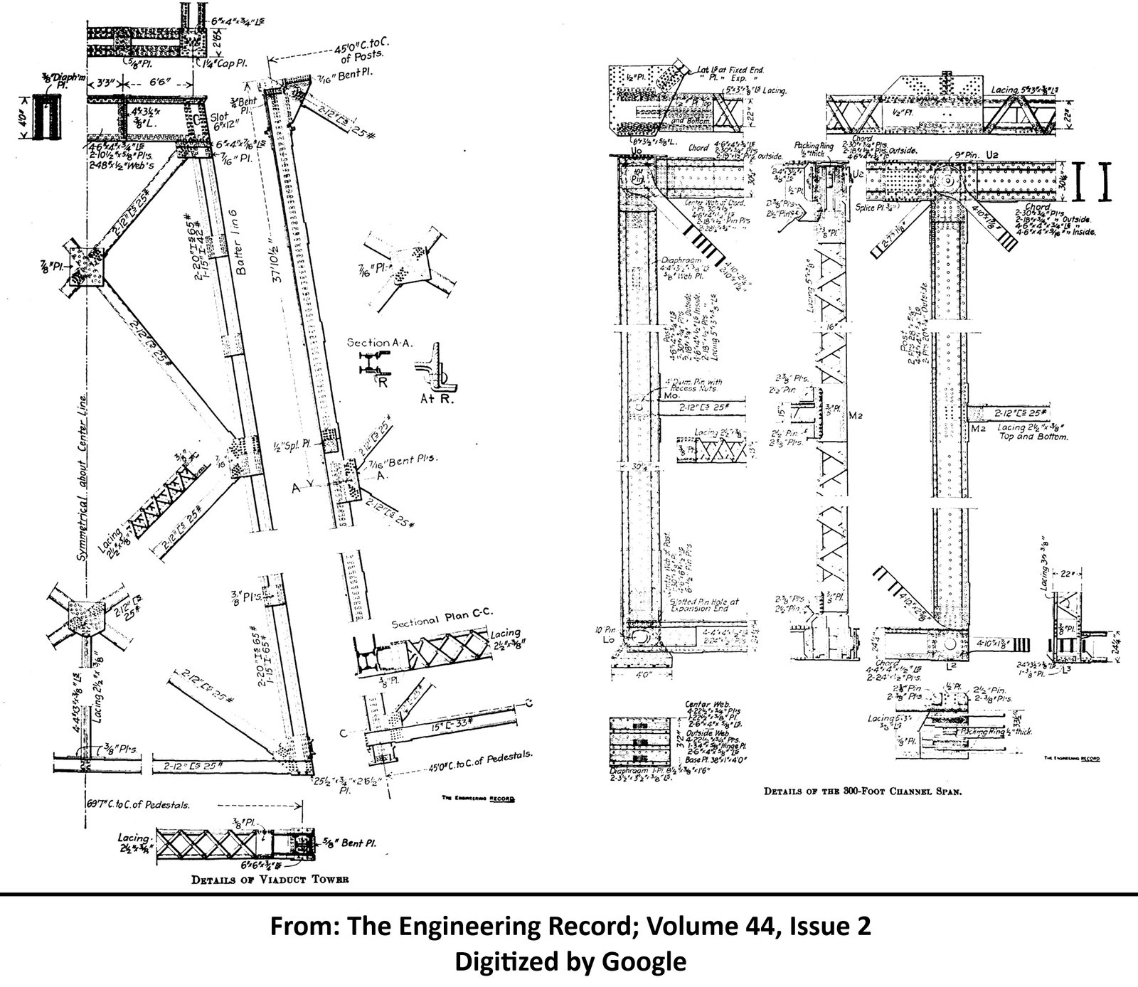
View historic articles discussing the construction of this bridge (digitized by Google)
View the Historic American Engineering Record documentation of this bridge
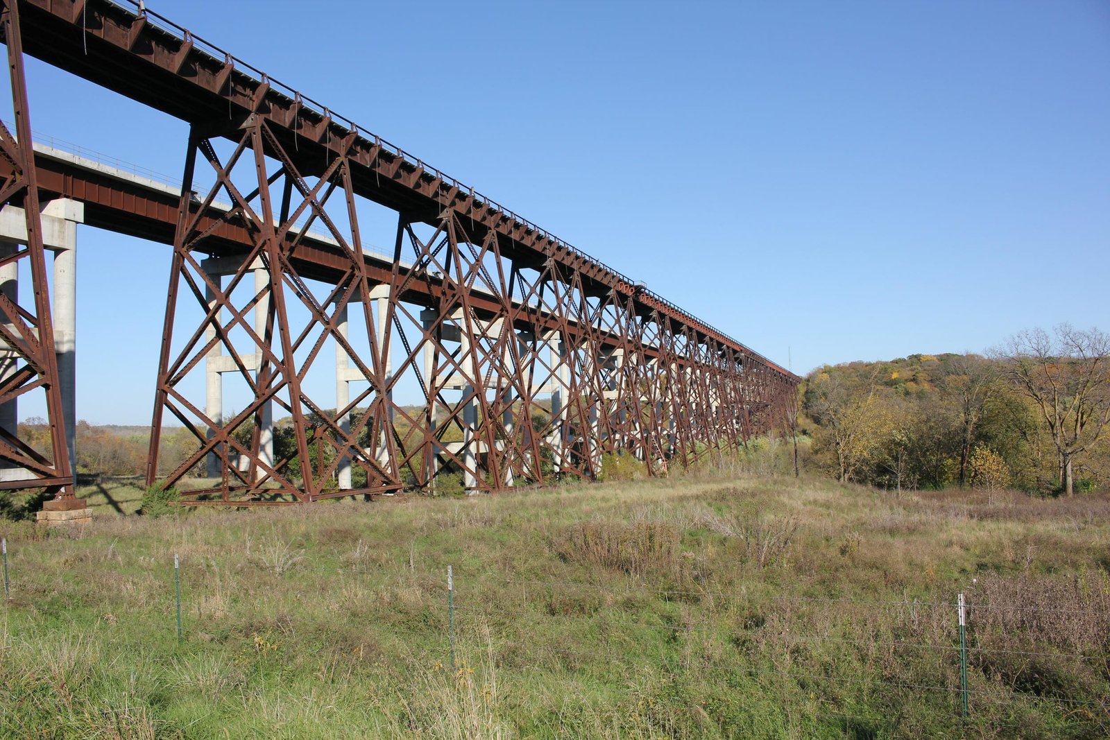
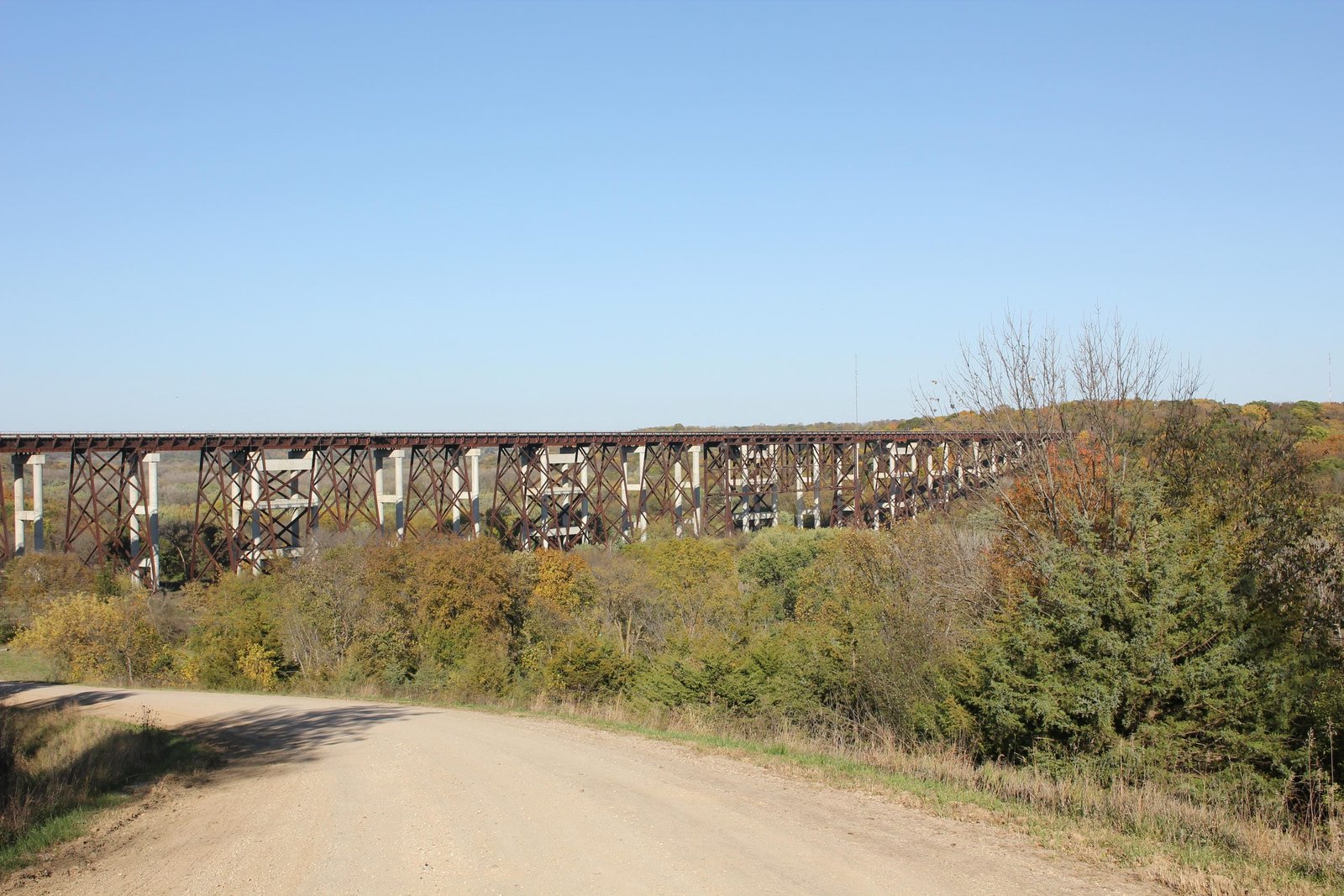
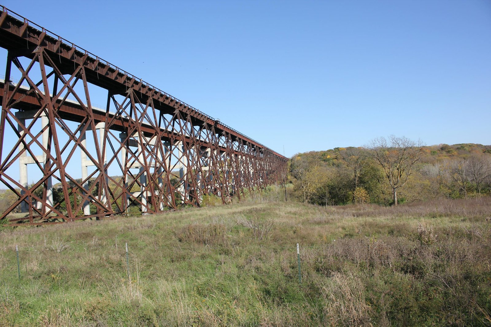
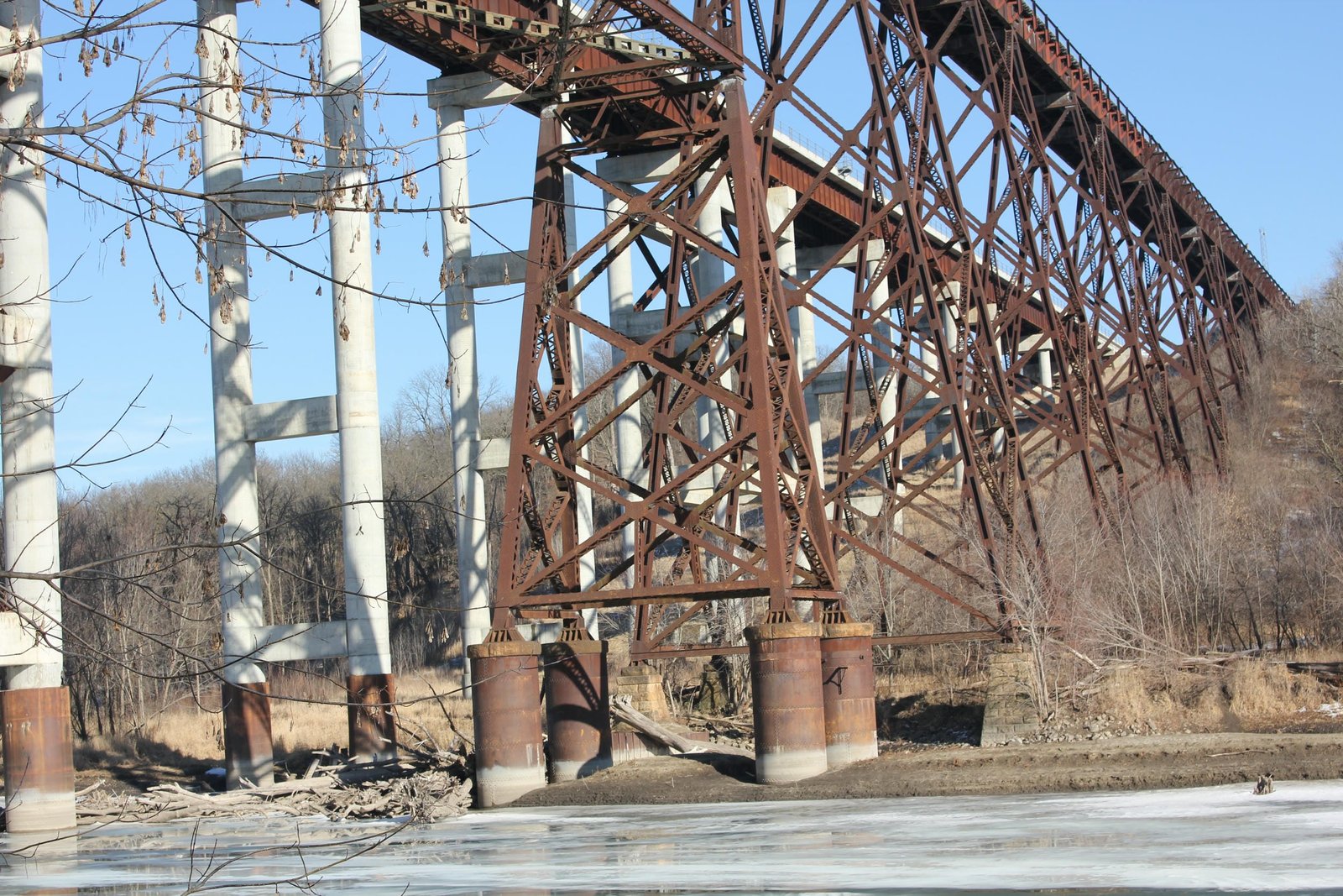
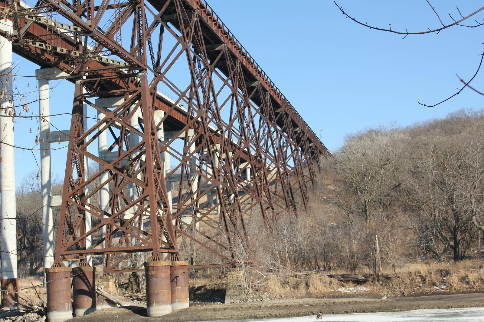
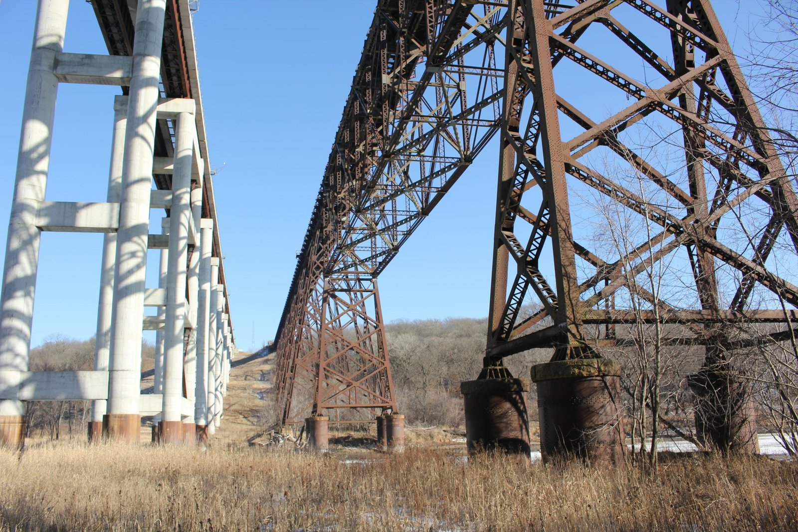
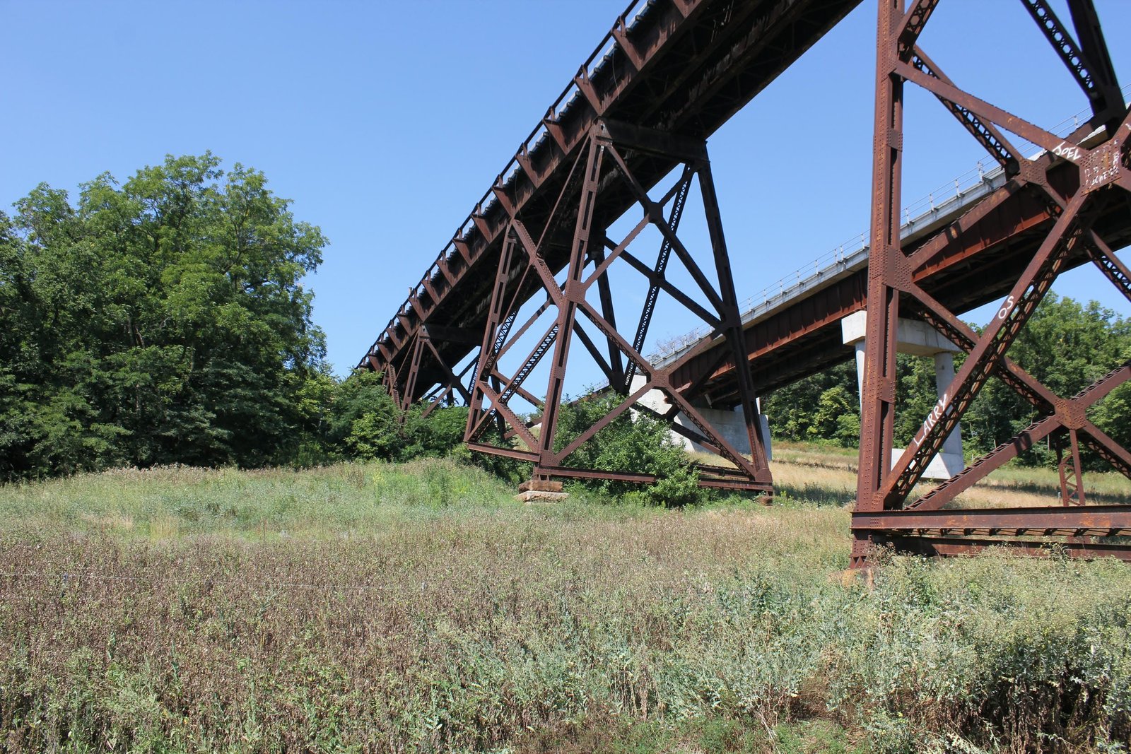
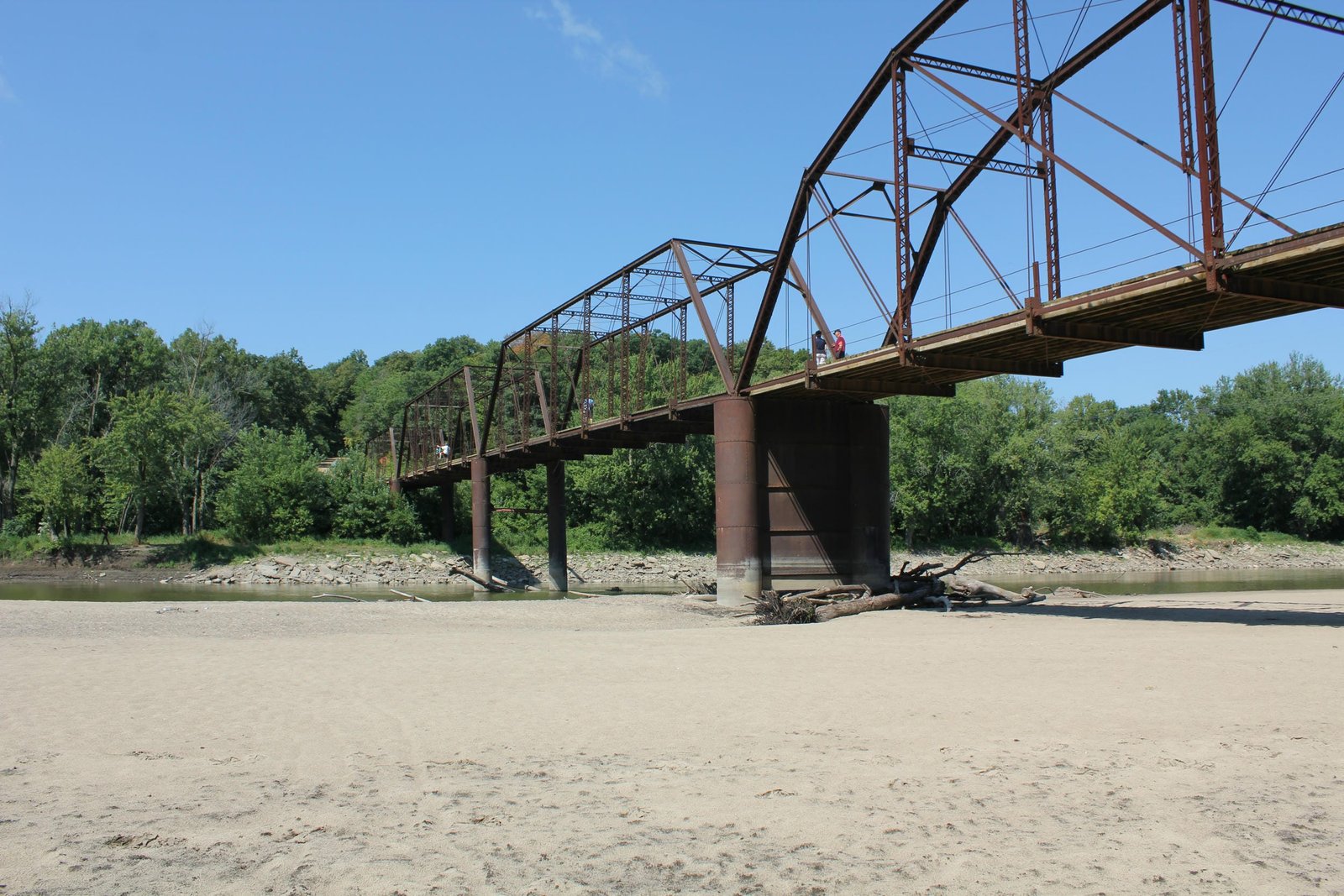
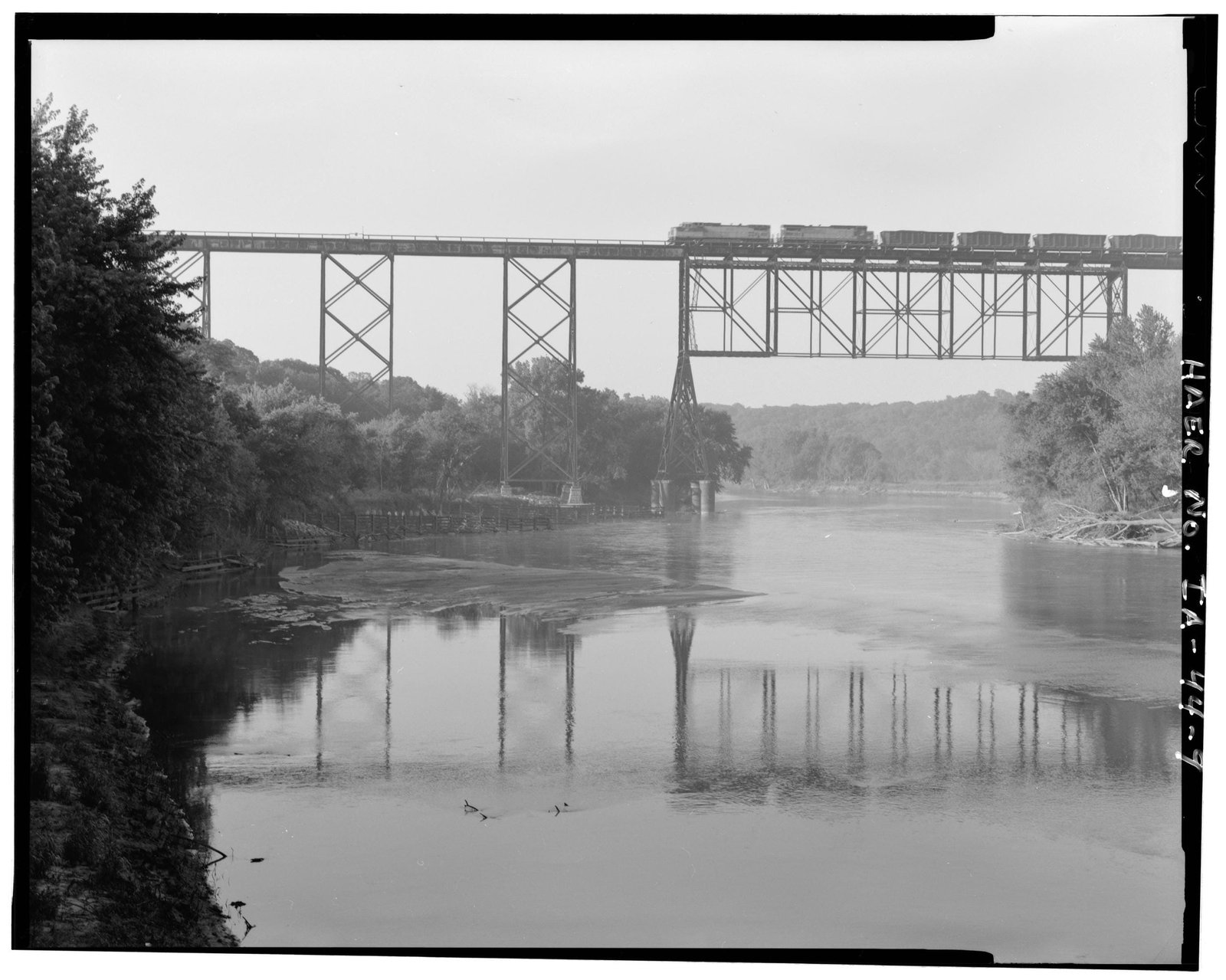
Located between Boone and Ogden, this iconic deck truss and deck plate girder viaduct carries a bypassed Chicago & North Western Railway mainline over the Des Moines River and Juneberry Road. Originally, the C&NW line turned southwest at Boone, following the Honey Creek valley, crossing the Des Moines River at Moingona and turning northwest towards Ogden. This original line had steep grades, several curves and was overall poor for operations. Starting in 1899, the C&NW sought to double track the line between Cedar Rapids, Iowa and Council Bluffs, Iowa. As part of the project, a double track cutoff was planned between Boone and Ogden, which would include a tall viaduct over the Des Moines River, eliminating the need for harsh grades. Preparation work for the new viaduct began in the spring of 1899. Drilling machines were used to drill test holes to determine the character of the ground. Contracts for the work were awarded in the summer of 1899. The chosen design would use a lengthy deck plate girder and steel tower viaduct, with a large deck truss center span. Actual construction work on the viaduct commended in the fall of 1899, when a temporary trestle was constructed across the river. All material was brought from Boone, and temporary quarters were erected near the bridge.
Construction on the stonework began on February 7, 1900. Soil borings determined that a thick layer of blue clay was present on the slopes near the ends of the bridge. It was decided to construct the abutments and outer tower footings using twelve to fourteen foot deep excavations. The bottom of these excavations was filled with beds of four to six feet of concrete, and stone was laid to form the pedestals. Closer to the river, timber piles were driven, concrete beds poured and stone masonry stacked to form the pedestals. The approach slopes were then graded around the viaduct footings, and an embankment constructed around the abutments. For the truss span tower footings, large steel shells were used. Four cylinders were used per tower, and they were pneumatically sunk. The process of sinking the cylinders consisted of riveting together one or two sections, pressurizing the cylinder and using concrete to sink the cylinder. The cylinders were sunk to between 42 and 46 feet deep, where they reached a sandstone layer. Work on the substructures was completed on June 6, 1900. With the exception of the tower copings, yellow limestone for the substructures was quarried at Mankato, Minnesota. Stone for the copings would use Abelmans Sandstone, quarried at Rock Springs, Wisconsin.
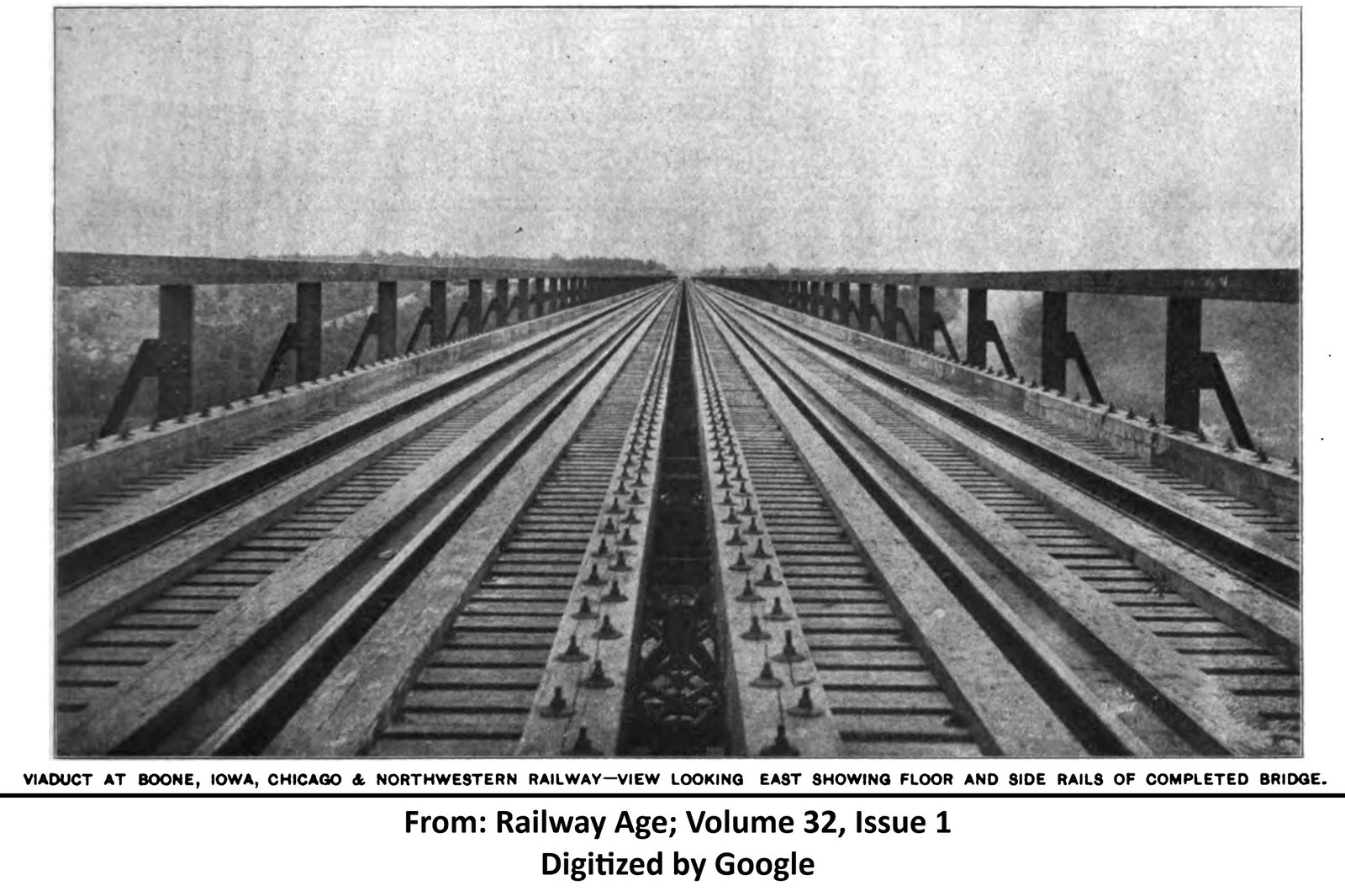
After the substructures were completed, preparation work for erecting the superstructure began. Throughout the summer of 1900, material for the superstructure was staged near each end of the bridge. Erection work on the superstructure commenced in early November 1900. Two derricks were used to at each end of the bridge to unload material arriving on railroad cars. Two travelers were constructed to lift and lower steel into position, and gas-powered pneumatic riveting machines were brought to complete all required field riveting. Work on erecting the bridge was commenced from each end of the bridge, with one traveler stationed at each end. Towers were raised by a cable system from the ground, while the deck plate girder spans were installed by placing the girders on the towers. At the center of the bridge, heavy falsework was used to erect the truss span. The two travelers met at the west end of the truss span, and on May 19, 1901; the bridge was opened to traffic. In total, the bridge used 5,680 tons of metal and cost $625,000 to construct. Almost immediately, the structure became the most iconic bridge along the Chicago & North Western Railway. When the bridge opened, it was considered to be the longest double track viaduct in the world. W.C. Armstrong penned an article about the construction of the bridge (included in the historic articles above), which was covered in most major trade magazines. In addition, the bridge quickly began being depicted in advertisements, memorabilia and photos, highlighting the first class facilities used by the C&NW.
While the bridge was originally officially known as the "Boone Viaduct", several newspapers and magazines began to refer to the structure as the Kate Shelley Bridge shortly after opening to traffic. Kate Shelley was a local heroine, who prevented a busy passenger train from plunging through a collapsed bridge along the original mainline. On July 6, 1881; heavy thunderstorms caused a flash flood of Honey Creek, collapsing a timber pile trestle bridge east of Moingona. Shelley, who lived near the collapsed bridge, knew that an eastbound passenger train was due within an hour. In the middle of a raging thunderstorm, the fifteen year old Shelley crawled across the Des Moines River bridge, reaching the station in time to save the train. She was quickly heralded a hero, and remained in the area throughout the rest of her life. She attended opening ceremonies of the new viaduct in 1901, and the viaduct was renamed in honor of her after her death. Over 140 years after the heroic act, the Kate Shelley story remains a well known piece of Iowa folklore.
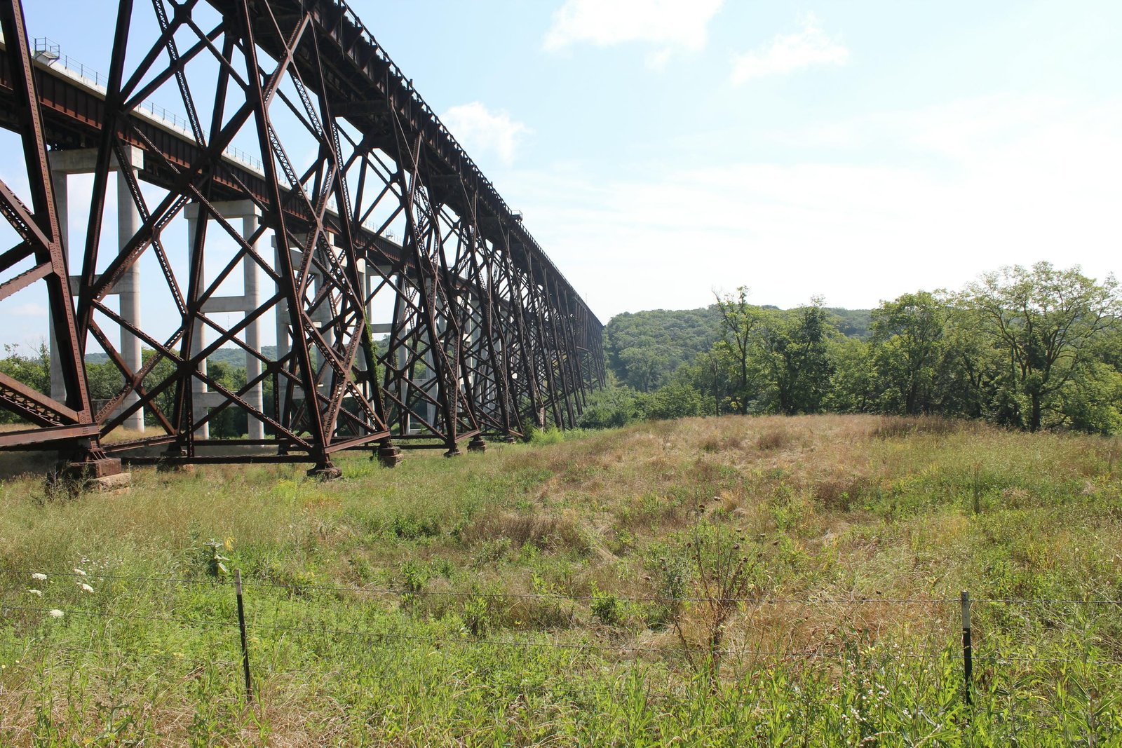
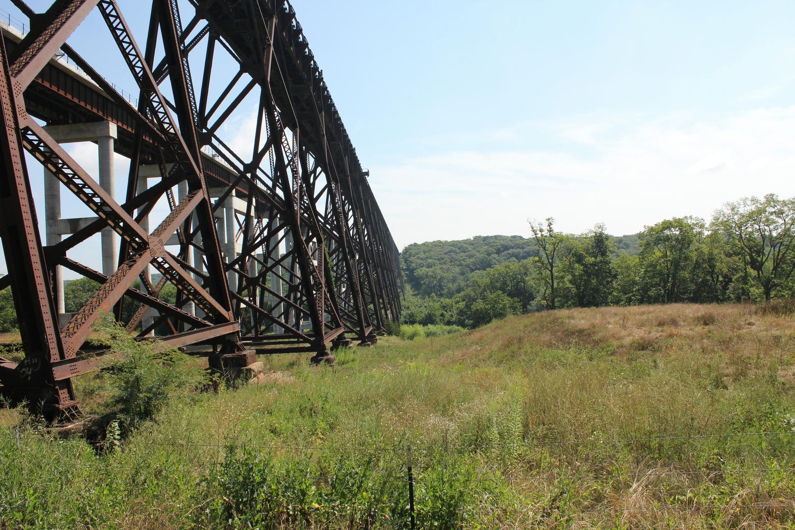
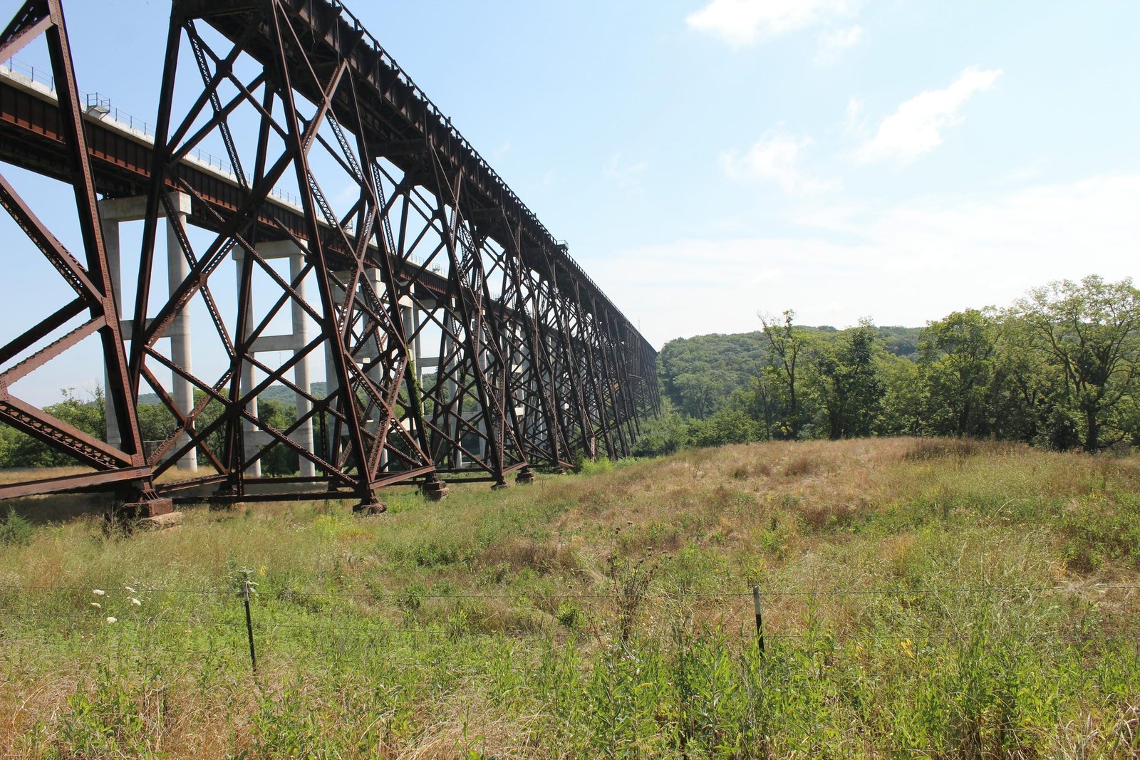
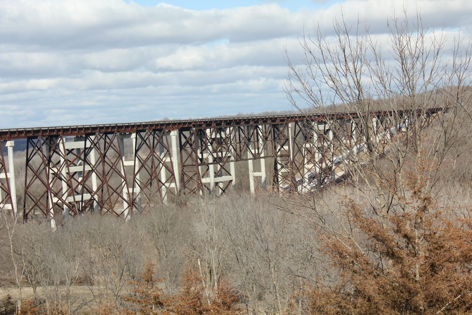
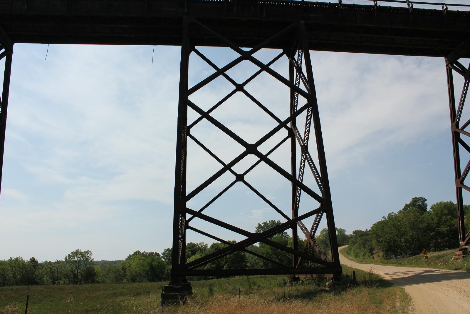
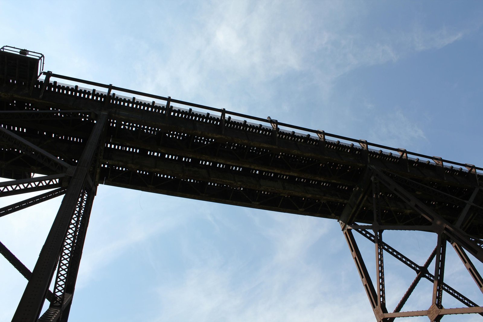
Beginning on the east end, the bridge consists of two 75-foot deck plate girder spans, set onto a rocker bent. Continuing west, the bridge uses six 45-foot deck plate girder tower spans alternating with six 75-foot spans of the same design. At the main rive channel, a 300-foot, 10-panel, pin-connected Baltimore deck truss span (span #15) is set onto two A-frame towers. The west approach consists of thirteen 75-foot spans alternating with twelve 45-foot tower spans. The approach towers use a typical design and are set on stone pedestals, while the truss span towers are supported by concrete filled steel cylinders. The entire length of the bridge is 2, 685 feet long, and the bridge is reportedly 185 feet high. Near the west end of the bridge, span #34 crosses Juneberry Road. The bridge was designed by William F. Finley of the Chicago & North Western Railway and famed engineer George S. Morison, who served as consulting engineer. W.C. Armstrong oversaw construction of the viaduct and served as the resident engineer of the double track cutoff between Boone and Ogden. The Widell Company of Mankato, Minnesota constructed the abutments and tower footings, while the steel cylinders were constructed by the Engineering Contract Company of New York City. When contracts for the bridge were awarded, three firms were awarded contracts for the steelwork. Union Bridge Company of Athens, Pennsylvania was awarded the contract for the truss span; Lassig Bridge & Iron Works of Chicago, Illinois for the girder spans and the Milwaukee Bridge Company of Milwaukee, Wisconsin for the towers. All three firms became part of American Bridge Company in 1900, and this firm finished fabricating the components.
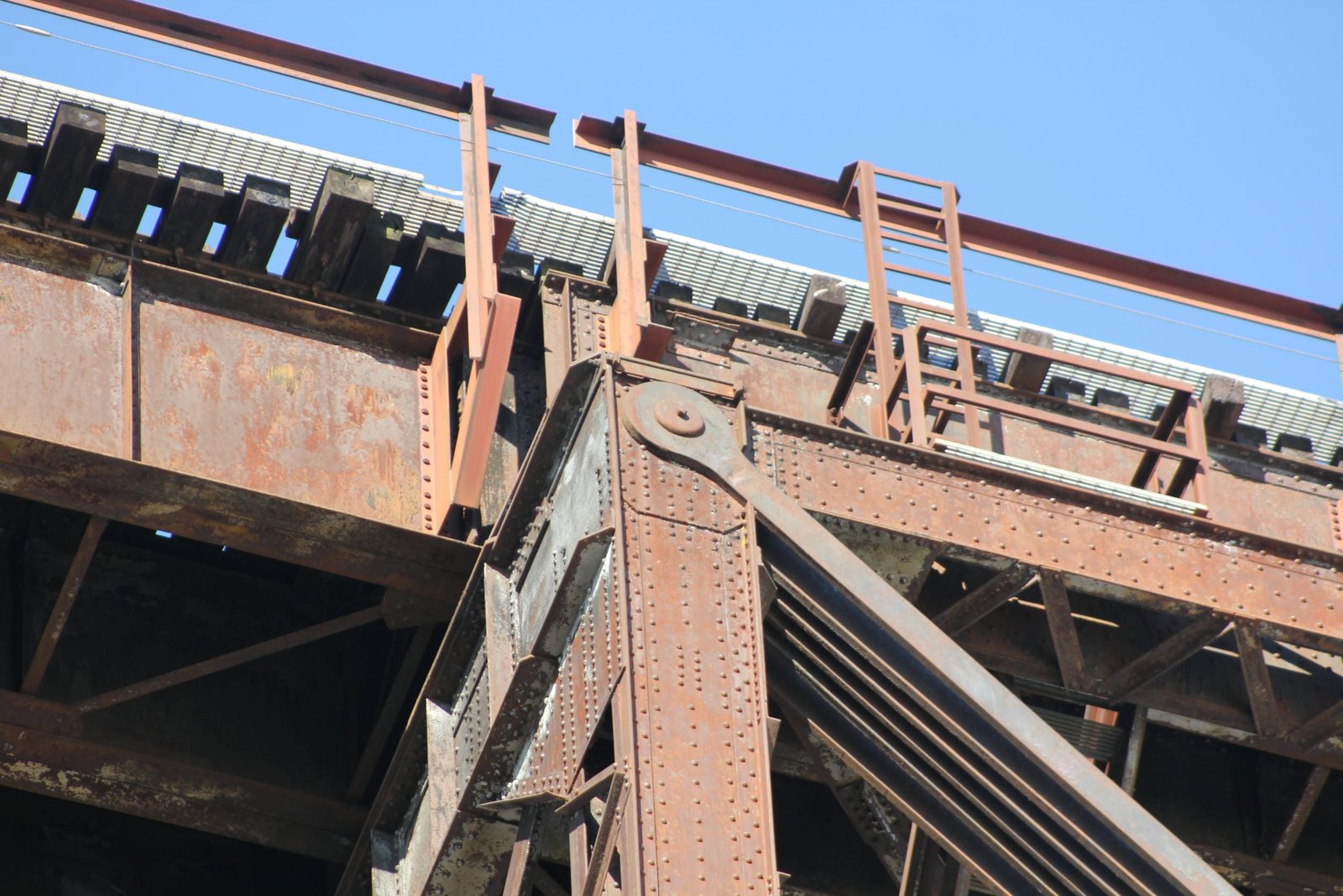
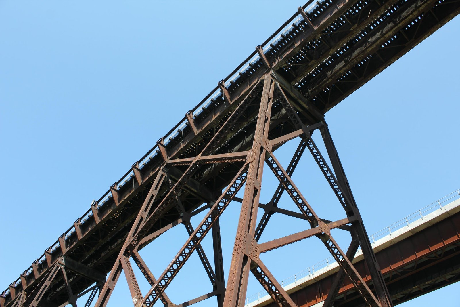
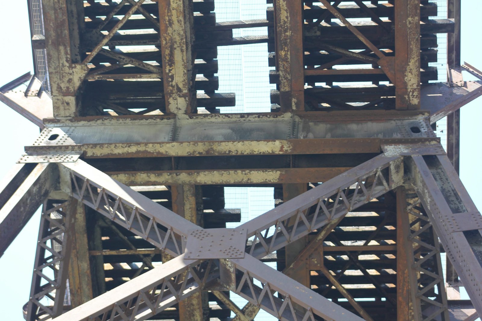
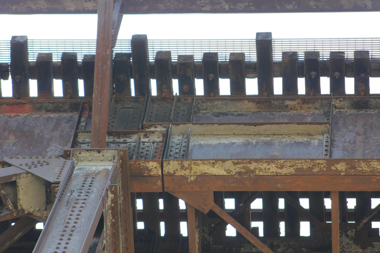
The truss span uses a heavy variation of a traditional design, with a combination of heavy eyebars and built-up members. The trusses are spaced at 30-foot centers, and are each 60 feet deep. Due to the Baltimore design, the truss span uses five standard panels, which are subdivided to create ten total panels. All connections to the top and bottom chords throughout the span consist of heavy pin connections. The top chord consists of built-up beams, which are V-laced on both sides. At the outer two subpanels on each end, the bottom chord also uses a V-laced beam. At the center subpanels, the bottom chord consists of eyebars. The diagonal members consist of eyebars, which are constructed in two lengths. The vertical posts consist of V-laced built-up beams, with the main vertical posts using a significantly heavier design than the subpanel vertical posts. Vertical posts at the subpanel points use a lighter bottom portion and a heavier top portion. Mid-level chords are used at six of the ten subpanels, and consist of light V-laced beams. Originally, V-laced beams were used for the transverse struts and lower lateral bracing. The floorbeams consist of plate girders seated above the top chord, and the stringers use two plate girders per track and are seated above the floorbeams. This design was chosen to minimize the height of the towers. Several repairs were made to the truss in 2001, which replaced some of the original members with bolted high strength steel. The deck plate girder spans follow a standard design, with two girders per track. A consistent depth of seven feet was chosen, for both the 75-foot and 45-foot spans.
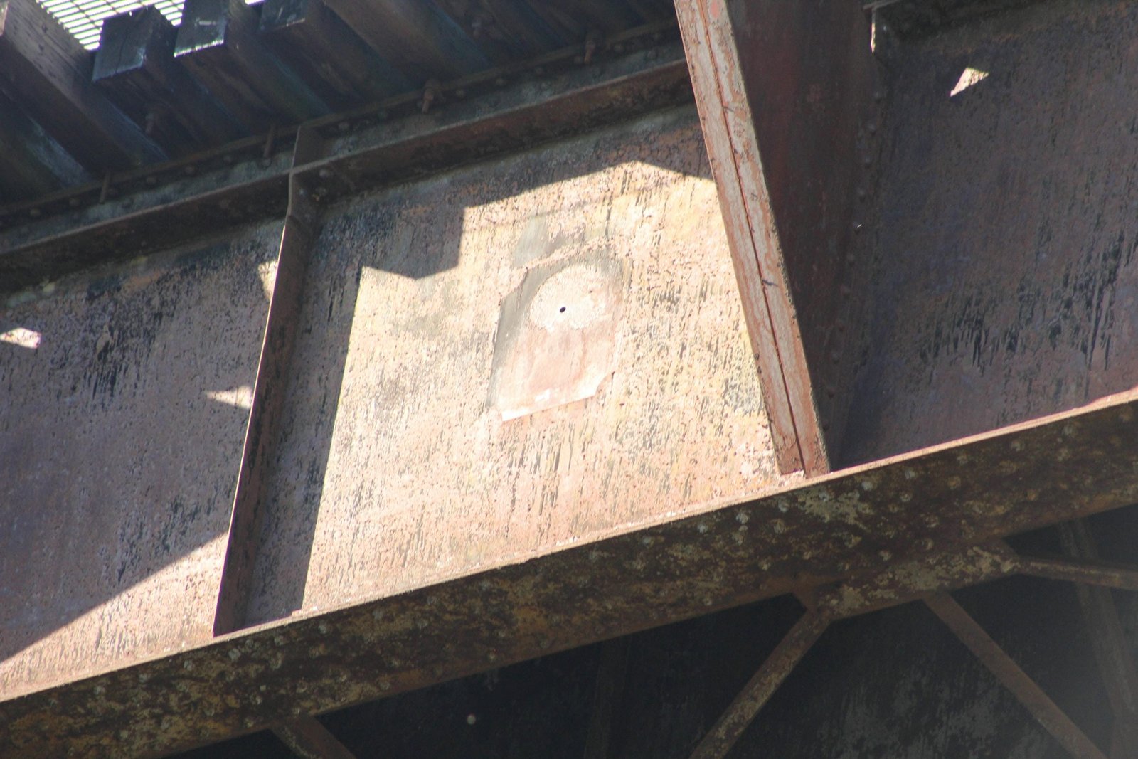
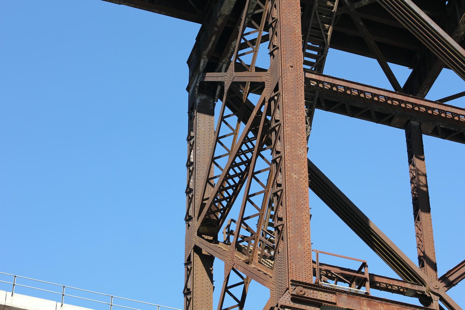
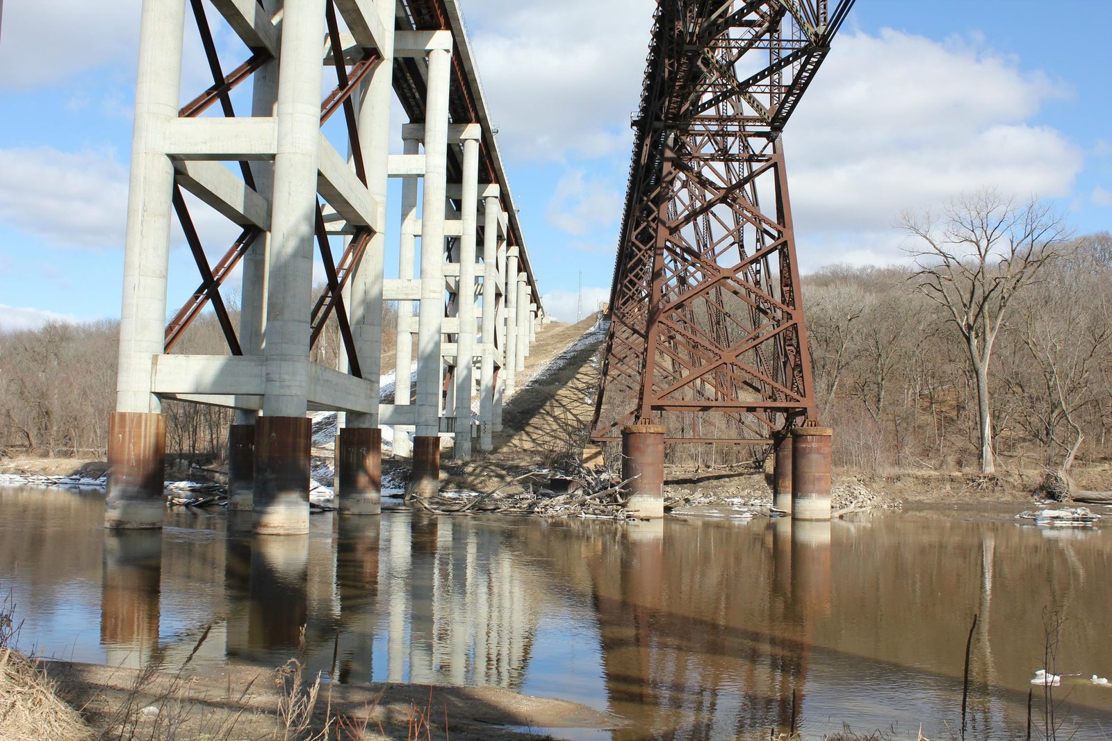
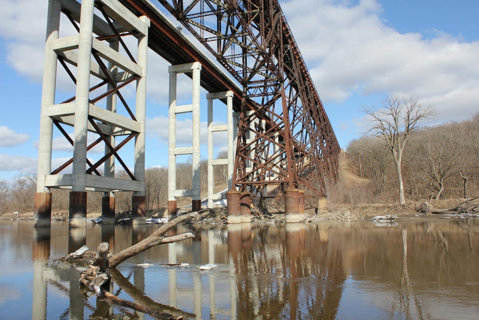
At each end of the truss span, an 80-foot tall steel tower supports the span. These towers are formed from four columns, which are connected by using both longitudinal and transverse V-laced beams at the base. At the top, two rows of transverse V-laced beams connect opposite columns. All four columns are connected by diagonal V-laced bracing. The columns are inclined to form an A-shape and two parallel columns are connected by a trapezoid shaped plate at the top. At the base, parallel columns are spaced at 27 feet, while they come to a point at the top. The two A-frame structures are spaced at a 30-foot spacing. Each column is set onto a concrete filled steel cylinder, which is capped with a sandstone coping. The cylinders are each ten feet in diameter and have a wall thickness of five-eights of an inch. The truss span is fixed by a roller bearing on the east tower and a pinned connection on the west tower. The approach towers are constructed of four columns, which are constructed of three I-beams riveted together. The columns are connected by transverse and longitudinal V-laced bracing at the base and by transverse plates at the top. Diagonal V-laced beams run both longitudinally and transversely, connecting the four columns. At the base, a vertical post connects the first level of diagonal bracing to the transverse bottom bracing. Each column is supported by a stone pedestal, which has a five foot by five foot cross section. A sandstone coping is placed on each pedestal, and the tower footings are fixed to the pedestals by large anchor rods. Each pedestal is set onto a thick bed of concrete far beneath the surface. At the tops of the towers, the girders are riveted to a plate, and the girders use an overhanging design to balance each other. The abutments consist of a standard square design, with large wedges buried beneath the surface. The abutments are also set onto a thick concrete pad, buried beneath the surface.
Girder viaducts on steel towers were often the most economical design for long, tall bridges crossing large valleys. While still complex to design and construct, these bridges were simpler and required less skilled construction than large masonry bridges or other steel designs. Large viaducts like this are relatively uncommon in the Midwest, as the terrain was generally flat and large embankments were avoided where possible. In Iowa, the Des Moines River between Fort Dodge and Des Moines runs through a deep valley, requiring either steep approaches or tall viaducts to cross. This bridge was the first of three notable viaducts constructed across the Des Moines River, with the Chicago Great Western Railway viaduct at Fort Dodge completed in 1903 and the Chicago, Milwaukee & St. Paul Railway (Milwaukee Road) viaduct between Madrid and Woodward completed in 1913. Similar to the Kate Shelley Bridge, the Madrid Bridge also used a double track design, while the Fort Dodge bridge was constructed for a single track. Of the three structures, the Kate Shelley Bridge was the longest and tallest, with the Fort Dodge bridge having a length of 2,582 feet and a height of 138 feet and the Madrid Viaduct having a length of 2,473 feet and a maximum height of 145 feet. The Fort Dodge bridge uses a similar Baltimore deck truss design with four shorter spans, while the Madrid Viaduct used riveted Warren deck trusses. Today, the Fort Dodge bridge is still in use, while the Madrid Viaduct was replaced by a new girder bridge in the early 1970s as part of a flood control project to construct Saylorville Lake. The replacement bridge was ultimately removed in 2004 and reused.
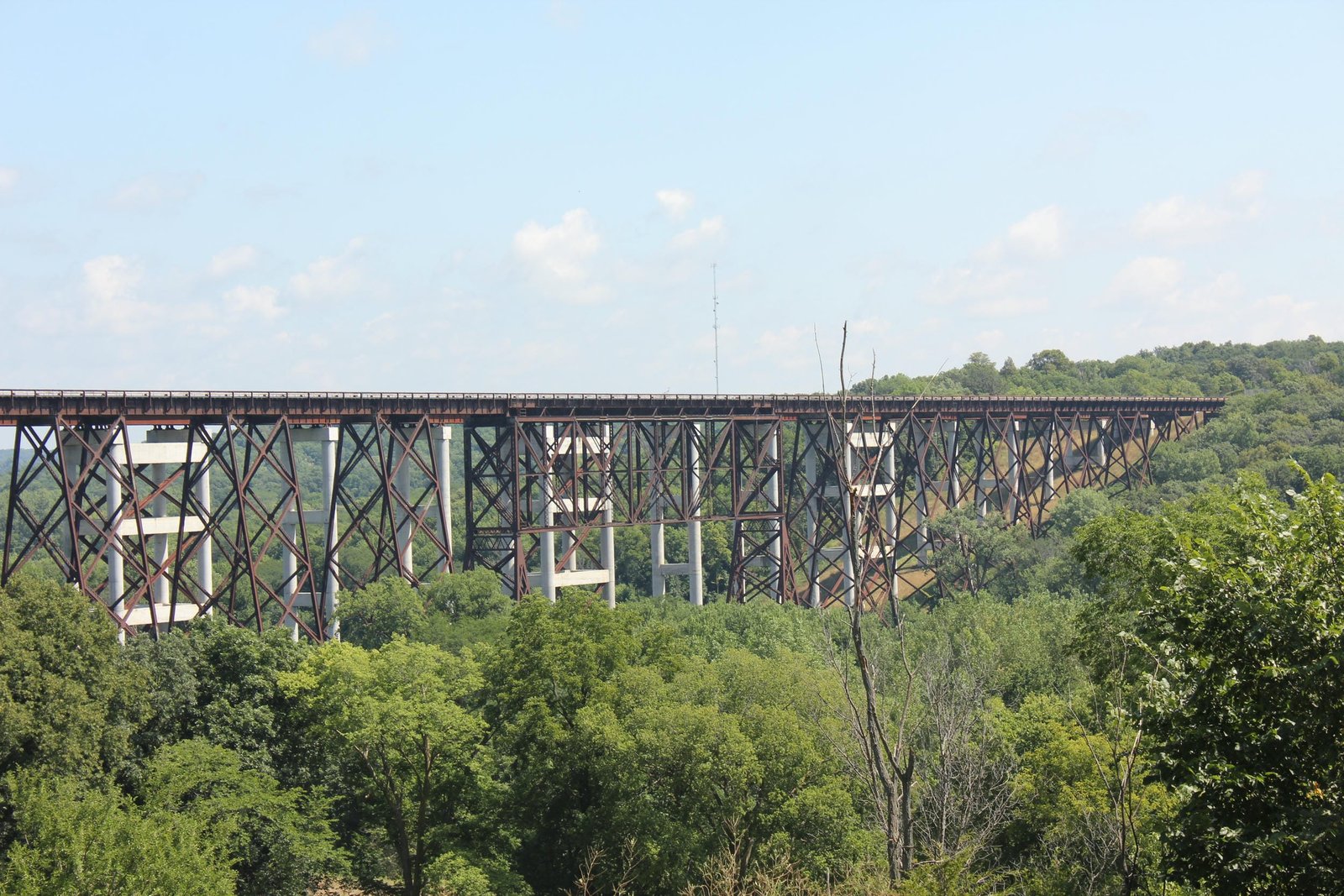
The Baltimore truss design was developed in the late 19th Century to allow for construction of longer pin-connected spans, without sacrificing economy or strength. While traditional Pratt spans were typically limited to approximately 200-foot lengths in extreme cases, Baltimore spans allowed for significantly longer spans to be constructed. This design remained popular throughout the early years of the 20th Century, before ultimately being superseded by other riveted truss designs. Deck plate girder spans were also popular for railroad use, as they were durable and easy to construct. Large steel towers became popular for bridges in the late 19th Century, due to the ease of construction and minimal amount of material required. By the 1950s, the bridge was limited to one train at a time. Several repairs were made throughout the 20th Century to strengthen the bridge. In 2001, a significant strengthening project was completed to improve loading capacity of the bridge. American Bridge Company was contracted to replace select components of the truss span. Despite this, it had become clear that the bridge was no longer a feasible long term solution to carrying the busy railroad over the Des Moines River. Between 2006 and 2009, a new bridge was constructed immediately north of the original structure. Upon completion, the original bridge was bypassed and fenced off, with the rails remaining on the deck. Overall, the bridge appears to be in fair to good condition, with no significant deterioration noted. Today, the bridge continues to remain bypassed but closed to traffic. It is unclear what the future holds for the landmark structure. The author has ranked this bridge as being nationally significant, due to the size, design and landmark status of the structure.
Citations
| Build date, engineers and builders (superstructure) | Railway Age; Volume 32, Issue 1 |
| Builders (substructure) | Marshalltown Evening Times-Republican; February 8, 1900 |
| Railroad History Citation | ICC Valuation Information, Compiled by Richard S. Steele |