


Click the photo to view the full-size version
| Name | Fort Madison Railroad Bridge Atchison, Topeka & Santa Fe Railway Bridge #231A |
| Built By | Atchison, Topeka & Santa Fe Railway |
| Currently Owned By | BNSF Railway |
| Superstructure Contractor | American Bridge Company of New York |
| Substructure Contractor | Union Bridge & Contracting Company of Kansas City, Missouri |
| Design Engineer | A.F. Robinson |
| Length | 3,347 Feet Total, 532 Foot Main Span |
| Width | 2 Tracks (Lower Level); 2 Roadway Lanes (Upper Level) |
| Height Above Ground | 15 Feet (Estimated) |
| Superstructure Design | Baltimore Through Truss and Deck Plate Girder |
| Substructure Design | Concrete |
| Date Built | 1927 |
| Traffic Count | 60 Trains/Day (Estimated) |
| Current Status | In Use |
| Atchison, Topeka & Santa Fe Railway Bridge Number | 231A |
| BNSF Railway Bridge Number | 231.49 |
| Significance | High Significance |
| Documentation Date | 6/19/2016 |
In 1873, the Chicago, Pekin & Southwestern Railway (CP&SW) began construction on 52 miles of new railroad, extending from Pekin to Pekin Junction, Illinois and from Eureka, Illinois to Ancona, Illinois. At the same time, the Chicago & Illinois River Railroad (C&IR) began construction on a 28 mile spur from Coal City, Illinois to Streator, Illinois, but work was soon ceased. The CP&SW purchased the incomplete line from Gorman to Streator, and connected it to Ancona. The CP&SW was purchased by the Chicago, St. Louis & Western Railroad in 1881, which constructed an additional 60 miles into Chicago, opening in 1884. The railroad was reorganized into the Chicago & St. Louis Railway (C&StL) in 1886. By the mid-1880s, the Atchison, Topeka & Santa Fe Railway (ATSF) was contemplating on extending their network from Kansas City, Missouri to Chicago, where the railroad could interchange with other large railroads. In 1887, the Chicago, California & Santa Fe Railway (CC&SF) began construction on 350 miles of new railroad, extending from Ancona to Sugar Creek Junction, near Kansas City. Work would be completed in 1888. The portion of the line from Ancona to Chicago would be reconstructed at this time to meet new standards.
The new line was leased to the ATSF in 1888, and fully absorbed into the ATSF in 1900. The line immediately became a core line for the ATSF, serving as part of the principal mainline (Chicago to Los Angeles) for the ATSF. During the first decade of the 20th Century, the Kansas City to Chicago line was extensively rebuilt for double track use. Within the City of Chicago, the tracks were elevated and subways constructed at street crossings. After the Amtrak takeover of passenger services in 1972, the line north of Bridgeport was abandoned in favor of other routes. Due to dwindling traffic, the route from Ancona to Pekin was abandoned in 1983 and 1984. In 1996, the ATSF was merged into Burlington Northern Railroad to form BNSF Railway, and a portion between Ash Street and Bridgeport abandoned. Today, BNSF operates this line as the Chillicothe Subdivision and the Marceline Subdivision. The line continues to be one of the heaviest used railroad routes in the Midwest.View an article describing the construction of this bridge
View the Historic American Engineering Record documentation for this bridge
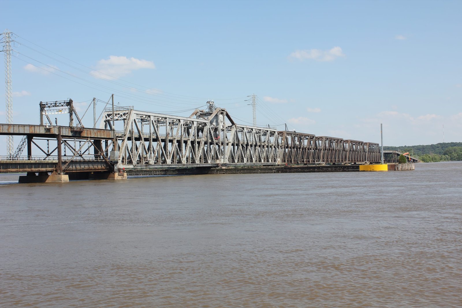
Located at Fort Madison, this massive through truss swing bridge carries the former Atchison, Topeka & Santa Fe Railway mainline and Illinois Route 9 across the Mississippi River. A charter for a bridge across the Mississippi River was first obtained in 1872 for a proposed railroad that would connect to Peoria, Illinois. However, this railroad line was never built, and a bridge was not constructed under this charter. In 1887, the Santa Fe began construction on a new mainline between Chicago and Kansas City, and the charter was surrendered to the Santa Fe. As part of the transfer, it was agreed that the bridge would be constructed for combined railroad and roadway use. Octave Chanute was retained to design a new bridge across the Mississippi River, which would carry combined railroad and road traffic. At the chosen location, a flat area was located along the Iowa shore, and the Chicago, Burlington & Quincy Railroad operated a mainline that followed the Mississippi River. A curve would be required to avoid crossing the railroad at an unusual angle, and to allow the new mainline to turn southwest. Work on the first bridge began in 1887, and was completed in 1888. The first bridge at this location consisted of a large through truss swing bridge, set onto stone substructures.
On the west end, the bridge was approached by two 150-foot, 6-panel, pin-connected Pratt through truss spans, which were constructed with one truss line longer than the other to accommodate a curve. The swing span consisted of a 398-foot, 14-panel, pin-connected Pratt through truss span, which used an inclined top chord and was balanced on a swing pier. The swing span was approached on the east by a 270-foot, 10-panel, pin-connected Parker through truss and four 234-foot, 9-panel spans of the same design. The swing span utilized a center bearing design, where wheels directly affixed to the swing span rotated on a track on the swing pier. Steel for the truss spans was fabricated by the Union Bridge Company at their Buffalo, New York plant. Stone for the piers was quarried at Stone City, Iowa; and the piers were founded by a combination of caissons and timber pilings, which were driven to bedrock. A roadway deck was attached to the outside of the bridge by use of brackets. The two Pratt through truss spans used a standard Union Bridge Company bracing, with an pedimented lattice design. The remaining spans used a variation of this bracing, with a heavier constructed arched lattice portal bracing.
The first bridge was constructed at a time when longer spans could be constructed without using a double intersection (Whipple) design. During the 1860s and 1870s, Whipple trusses were commonly used by railroads, as they allowed for durable long spans. However, these spans began to fall out of popularity in the 1880s, as the design was unpredictable and subject to uneven loading. Single intersection (Pratt) spans were commonly used for lengths under 200 feet, and had become the standard truss design for spans of this length during the 1870s. To construct longer spans using this design, the trusses needed to be taller. To minimize the amount of material required, Parker through trusses became popular for this application. These spans used an inclined top chord. The Parker spans on the first bridge utilized a polygonal shape, with the top chord flat at the center two panels. The truss spans of the first bridge are believed to have been early examples of the Parker through truss design.
In the first years of the 20th Century, the Santa Fe double tracked the line between Kansas City and Chicago. However, the bridge was not reconstructed for two tracks until later. The bridge was converted to a gauntlet track, where two tracks use the space of one track, which avoids the use of switches. This configuration served as a temporary solution until a larger bridge could be constructed. By the 1920s, traffic had significantly increased on this line, and the bridge was no longer capable of carrying increasingly heavy trains. In addition, the old bridge crossed the river at a right angle, providing operational issues for the railroad. In the early 1920s, the railroad began investigating a solution for a new bridge. By the mid-1920s, it had been decided to construct a new bridge upstream on a new alignment, which allowed for 50-degree curvature at either end of the bridge. To accomplish this, the new bridge would cross the river at a 65-degree angle. In addition, by placing a new bridge upstream, the railroad could avoid disruption of railroad traffic on the old bridge. Another design consideration was the location of a new roadway deck. The arrangement of placing the roadway outside of the trusses on the old bridge had become obsolete, and it was decided to construct a new roadway deck above the railroad deck across the main spans, and as part of a parallel viaduct on the approaches. Plans for the new bridge were prepared by Santa Fe Bridge Engineer A.F. Robinson, and contracts were awarded in 1925 to Union Bridge & Construction Company for the construction of the new substructures, and to American Bridge Company for the fabrication of the steel. Work on the bridge and new approach embankments began later that year.
Throughout 1926, construction continued on the bridge. Provisions were made to allow for the placement of concrete during the winter, an unusual construction sequence for the time. By 1927, the bridge was complete, and traffic was switched to the new bridge. The old bridge was demolished in 1928, and it is currently unknown if any portions of the old bridge were reused elsewhere on the Santa Fe system. The entire project cost approximately $5,500,000. Because preliminary borings revealed that bedrock was nearly 165 feet below the low water elevation, it was not practical to sink caissons to bedrock. Instead, the main piers are founded on caissons, which were sunk to a depth of approximately 70 feet. These caissons are supported by sand, which allowed for a shallower design. The approach piers are supported on timber piles, which are driven to a similar depth. All substructures of the bridge are heavily reinforced and devoid of any decorative features.
The superstructure of the bridge consists of three distinct components, including the swing span, the fixed truss spans and the approaches. The swing span consists of a 535-foot, 14-panel, riveted Baltimore through truss span, which is set on a hollow concrete swing pier. This span utilizes two 266-foot spans, which are joined by a large tower at the pier. To accommodate the angle of which the bridge crosses the river, the swing span was constructed at a 65 degree skew. The swing span is a rim bearing type, where the superstructure is directly affixed to a metal drum, which turns on a track of rollers known as the roller nest. Loading from the swing span is transferred to the radial girders of the drum by use of eight articulated points, an unusual feature of this bridge. To accommodate this feature, the lower chords were specially designed and were the largest individual pieces fabricated for the bridge. Each center section of the lower chord of the swing span is 41 feet in length, and has a weight of 61 tons. The tower of the swing span utilizes built up vertical members and steel bars for the tension members. A machinery house is located above the roadway deck on the center tower, and stairs were built on either side of the tower to access it. A tollbooth on the roadway deck is located in the center of the tower, and the current toll for passenger vehicles to cross the bridge is $2. Built up members are used for all portions of the trusses, except for the connections to the towers, which consist of eyebars.
Approaching the swing span to the east, the bridge utilizes four fixed truss spans. Each of these truss spans consists of a 270-foot, 7-panel, riveted Baltimore through truss. The fixed trusses are similar in design to each half of the swing span, and consist of massive built up members and a Warren style portal. All trusses of the bridge are built taller than normal, to avoid placing the roadway deck on top of the truss. The railroad west approach consists of one 99-foot and eight 80-foot deck plate girders, while the roadway approach uses through girders of the same size. The railroad east approach consists of nine 100-foot deck plate girders, and the roadway approach uses through girders of the same size. The roadway approaches are generally set onto steel bents and towers, which share concrete piers with the roadway approach. On the west approach, the roadway is placed on the north side of the tracks, and on the east approach, the roadway is placed on the south side of the tracks. The closest span to each end of the main trusses is set directly above the railroad, while the second span is angled and set on a steel tower. The roadway deck is constructed of concrete, while the railroad deck uses a ballast deck.
The use of a swing span instead of a vertical lift span for this bridge is a notable feature. In the early 20th Century, vertical lift spans became the standard for movable bridges. Swing spans required a center pier, which generally divided the navigation channel into two smaller channels. The use of the Baltimore through truss design is also noteworthy. This design was created in the 1890s to allow for longer spans using a variation of the Pratt design. Early versions of this design used pinned connections, however this span uses riveted connections. The Santa Fe constructed a number of Baltimore through truss bridges in the late 1920s and early 1930s, using a similar design to this bridge. Since the initial construction, the bridge has seen a number of changes. The original decks of both the railroad and roadway have been replaced, most recently in the 2000s. Other repairs, such as strengthening of some members, has been noted. Overall, the bridge appears to be in fair to good condition, with no significant deterioration noted. Today, the bridge continues to carry heavy railroad traffic, and is still a major Mississippi River crossing for automobiles. The author has ranked this bridge as being highly significant, due to the double deck design, large size and history of this crossing.
Citations
| Builders and build date | Railway Age; Volume 83, Issue 2 |
| Railroad History Citation | ICC Valuation Information, Compiled by Richard S. Steele |