


Click the photo to view the full-size version
| Name | Redstone Bridge Chicago & North Western Railway Bridge #432 |
| Built By | Chicago & North Western Railway |
| Currently Owned By | Canadian Pacific Kansas City Limited |
| Superstructure Contractors | Rust and Coolidge of Chicago (Swing Span) Leighton Bridge & Iron Works of Rochester, New York (Approach Spans) |
| Substructure Contractor | Unknown |
| Engineer | Unknown |
| Length | 880 Feet Total, 206 Foot Main Span |
| Width | 1 Track |
| Height Above Ground | 30 Feet (Estimated) |
| Superstructure Design | Camelback Through Truss, Quadrangular Lattice Through Truss and Timber Pile Trestle |
| Substructure Design | Stone Masonry and Timber Pile |
| Date Built | 1880, Rehabilitated 1909 and c. 2002 |
| Traffic Count | Less than 1 Train/Day (Estimated) |
| Current Status | Open To Traffic But Used Sparingly |
| Chicago & North Western Railway Bridge Number | 432 |
| Significance | National Significance |
| Documentation Date | 9/4/2011; 11/12/2011; 5/30/2015 |
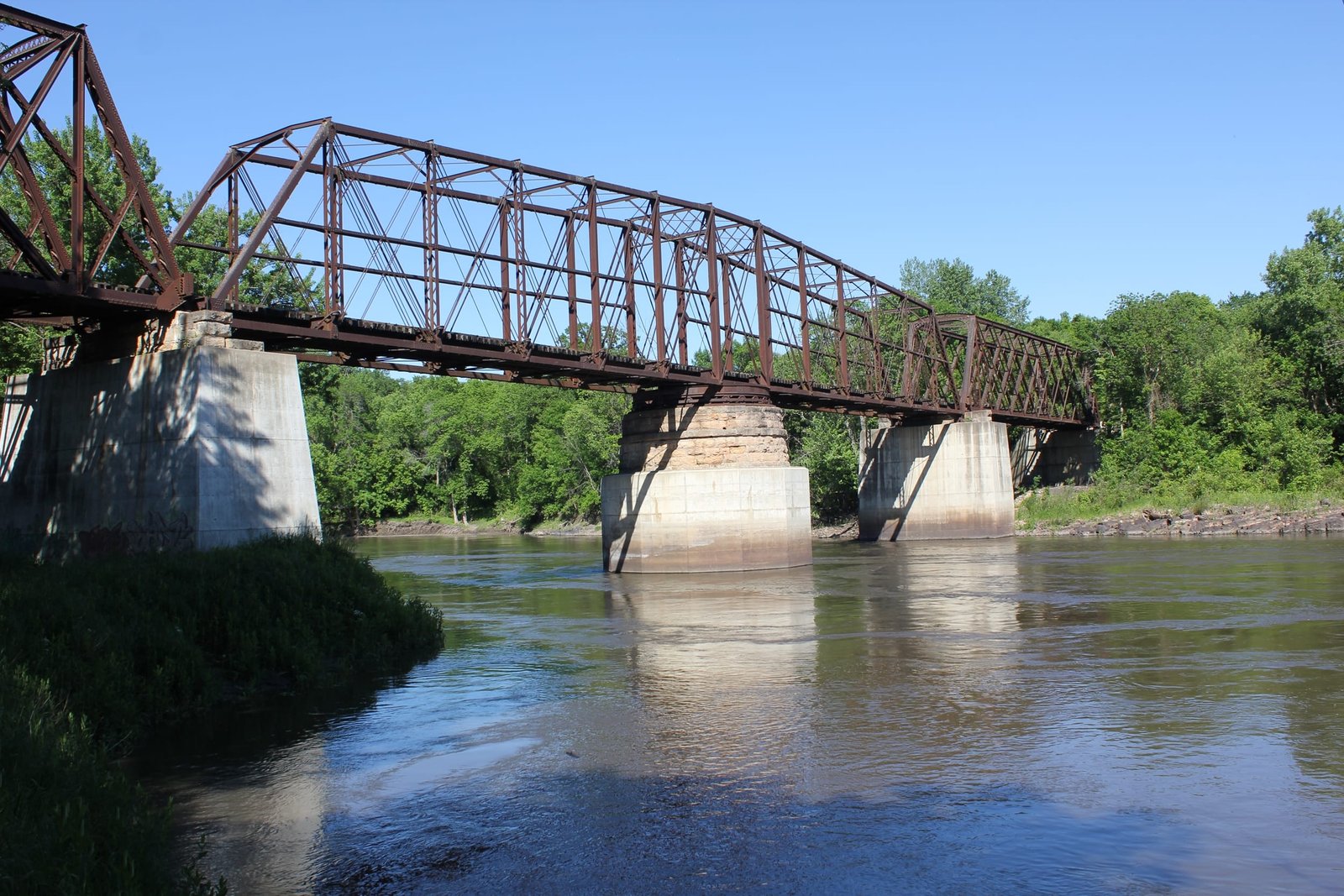
Located in the woods and nearly forgotten, the oldest railroad truss bridge in Minnesota crosses the Minnesota River east of New Ulm. This unique wrought iron bridge is one of the most historically significant bridges in the United States. The first bridge at this location consisted of a timber truss swing span, set onto timber substructures and approached by lengthy timber pile trestle approaches. Between 1880 and 1881, the bridge would be reconstructed with the present structure. The bridge features a 206-foot center pivot 13-panel Camelback through truss swing span, with unique pinned connections. The swing span is approached by a single 130-foot, 11-panel, riveted quadrangular lattice through truss span on either end. These spans contain design features typical of early spans of this design. The bridge is approached by 33 spans of timber pile trestle on the west end, which has been shortened since the initial construction. The truss spans are set onto stone substructures, of which all but one have been encased in concrete. The stone substructures were constructed by an unknown contractor using stone quarried at Kasota, Minnesota. Rust & Coolidge fabricated the swing span, while the Leighton Bridge & Iron Works fabricated the approach spans.
The swing span uses a number of design features which are typical for the era. In addition, a number of features were added during a 1909 strengthening of the bridge. The upper and lower chords consist of a square channel, which is covered by a plate on three sides and V-lacing on the bottom. The endposts use a similar design, use a light V-lacing on the back side , and are set a standard incline (photo #74, above). Vertical members of the span use a combination of solid rolled beams and built-up members with light V-lacing (photo #52). The portal bracing uses a non-decorative bracket style bracing (photos #36 and #55), while most sway bracing uses a similar design (photo #51). The sway bracings on either side of the center panel use an attractive lattice design (photo #53). The diagonals consist of a combination of eyebars and rods, the latter of which was added during the 1909 strengthening. Both the upper and lower lateral bracings use rods, which are inserted through the upper and lower chords. The floor is constructed of a traditional design, with floorbeams using a solid trapezoidal plate. The stringers consist of I-beams placed in two sets of two, which are fastened to the floorbeams with angled plates. The floorbeams were originally connected to the lower chord with riveted gusset plates. Post-tensioning rods were added to the floorbeams, which use a U-shape which is wrapped around top corner of the floorbeam (photos #21 and #33). These rods are tightened with turnbuckles. In addition, the original stringers appear to have been replaced at this time. A longitudinal bracing was also added approximately halfway up the truss (photo #52). Additional sections of riveted plates were added to the upper and lower chords, particularly near the connections (photos #5, #6 and #7). Additional diagonals were also added to the outside panels of the truss at this time. In addition, the lower angle connections have been strengthened with riveted square plates. These alterations were not made in 1909, and were likely made in the mid-20th Century.
The connections of the swing span uses a number of unusual features, some of which is the result of the 1909 strengthening. The original design used eyebars, which are connected to the lower chord by pins. The outer panels have been strengthened by adding two rod diagonals, which use an unusual U-bolt connection to the lower and upper chords. The rods are placed through a plate, which is held together using bolts (photos #8, #21 and #22). The inner panels appear to have had limited strengthening. These connections consist of a pin connection, which fastens a gusset plate to the upper and lower chords. The diagonal members are fastened to this gusset plate by an additional pin (photo #50). Other connections use a more traditional design of eyebars around a single pin (photos #5, #6 and #29).
The swing span uses a rim bearing design, where the superstructure is set onto a metal drum, which rotates on wheels. Despite the Minnesota River having lost navigable status past Mankato in approximately 1884, many of the swing features of the bridge have been retained. While the roller bearings on either end have been removed and solid bearing blocks installed (photo #35), the swing mechanism is fully intact. The center of the swing span is balanced on a stone column, located in the center of the swing pier (photo 23). A metal wheel is located at the top of this column (photo #28), and rods radiate outwards, which are connected to rollers (photo #25), placed on a circular geared track (photo #30). An iron drum is located over these wheels (photo #9), and additional floorbeams and stringers are located over the drum (photo #26). The superstructure was turned by placing a "T" shaped key over a square nut (photo #54), which turned a gear system to rotate the drum and superstructure along a geared track (photos #24 and #27). Portions of the drum, gears and bracing were forged by the Trenton Iron Company and the Union Roller Mill Company. It is believed that the end rollers were removed during the later strengthening project.
The approach spans use a traditional lattice truss design for the era. The upper and lower chords of the spans consist of channels, which are riveted together and braced with plates at the connections. The upper chord uses a V-lacing on the top over the end panels, and a solid plate over the center of the span (photo #17). Endposts consist of a similar design, which is braced with diagonal plates between the channels. Upper and lower lateral bracings consist of solid plates, which are riveted to the chords (photos #13 and #48). The diagonals consist of a combination of tightly laced members and solid plates (photo #19). The outside panels of the bridge use a crash bar, typical for this design. Also typical of this design, the diagonals are fastened directly to the chords by use of rivets (photos #10, #11, #12 and #18). Similar to the main span, the approach spans use a traditional floor design, consisting of a trapezoidal floorbeam and two sets of two I-beam stringers (photo #13). The approach spans have also been strengthened with a post-tensioning rod, which is wrapped around the top of the floorbeam (photo #16). Portal bracing of the approach spans consists of a pedimented lattice style bracing, typical for this design of truss in the late 1870s and early 1880s (photo #20). The sway bracing consists of solid channels (photo #48). During the 1909 strengthening, the stringers appear to have been retained, while additional plates were added to the lower angle connections of the spans (photo #75). These additions use bolts, which contain square heads and square nuts, and were likely added in the mid-20th Century.
Although the lattice truss design was popular in Europe, few American railroads utilized the design. While Union Pacific Railroad, the Chicago, Rock Island & Pacific Railway and a handful of eastern railroads utilized the design to various extents, no railroad constructed as many lattice truss bridges as the C&NW. Between 1878 and 1930, through trusses constructed by the C&NW nearly exclusively used this design. Although lattice trusses were not popular with American railroads after the 1880s, the C&NW relied heavily on this design, as it had proven to be resilient towards derailments and damage. The main drawback of the design was the unpredictable nature, as the structure was not statically determinant. The lattice truss design appears to have first been introduced to the C&NW by Leighton Bridge & Iron Works, which constructed some of the first iron lattice trusses for railroad use.
Since the original construction of this bridge, a number of alterations have been made to the bridge. The most significant alteration to the superstructure came during the 1909 strengthening, although additional alterations appear to have been made in the mid-20th Century. Additional alterations were made between 1992 and 2003, when most of the stone substructures were encased in concrete. The only remaining stone substructure not encased was the west pier. Due to the unique design of the bridge and excellent historical integrity, the author has ranked this bridge as being nationally significant. Overall, the bridge appears to be in fair to good condition, with little deterioration noted within the iron components of the bridge. While the State of Minnesota attempted to list this bridge on the National Register of Historic Places, the railroad blocked this listing. The only traffic over the bridge is traffic serving the quarry on the east end. It appears that little traffic crosses the bridge today. The author has ranked this bridge as being nationally significant, due to the extremely historic nature of the structure.
Citations
| Build Date | Chicago & North Western Railway Valuation Notes at the Chicago & North Western Historical Society Archives |
| Builder (main span) | The Railroad Gazette: Volume 12 |
| Builder (approach spans) | Leighton Bridge and Iron Works plaque |
| Railroad History Citation | ICC Valuation Information, Compiled by Richard S. Steele |